|
|


 Arabic
 Bengali
 Chinese
 English
 French
 German
 Hebrew
 Hindi
Hindi Italian
 Japanese
 Korean
 Malay
Malay Polish
 Portuguese
 Spanish
 Turkish
 Ukrainian
 Vietnamese
|
ENCYCLOPEDIA OF RADIO ELECTRONICS AND ELECTRICAL ENGINEERING Small-sized switching power supply 12 volts 2 amps. Encyclopedia of radio electronics and electrical engineering
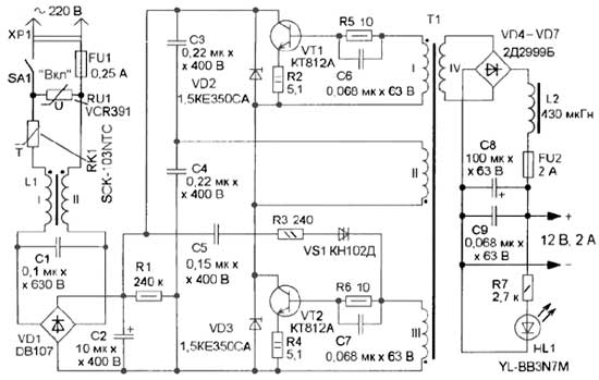
Encyclopedia of radio electronics and electrical engineering / Power Supplies The proposed self-generating SMPS (switching power supply) has small dimensions and high efficiency. Its peculiarity is that the magnetic circuit of the pulse transformer works with entry into the saturation region. When designing self-generating SMPSs, in most cases, a powerful transformer is used in linear mode, and a low-power switching transformer is used in magnetic circuit saturation mode. The individual windings of these transformers are connected in series with one another and with a current-limiting resistor - this is how a positive feedback circuit (PIC) is formed. The disadvantage of this solution is the increased heat generation in this resistor. The desire to reduce the power dissipated by this resistor, in most cases, leads to an increase in the heating of switching transistors and a decrease in efficiency. The low efficiency forces developers to pay attention to other circuitry solutions for converters, for example, Royer oscillators. They have a transformer with a saturable magnetic circuit, and they do not have a low-power switching transformer and a current-limiting resistor. However, a current flows through the switching transistors at the moments of switching, the amplitude of the pulse of which can exceed the average value of the current consumed by 3 ... 20 times. This circumstance not only dictates the choice of transistors with a large current margin, but also manifests itself in their increased heating. The efficiency of such a SMPS is approximately 50% at an output power of up to 30 W. The efficiency can be increased by including low-resistance resistors in the emitter circuits of the switching transistors. This is exactly what is done in the IIP, the scheme of which is shown in Fig. 1.
At first glance, it may seem that this will only lead to increased heat generation on these resistors. But thanks to these resistors, there is a local negative feedback (NFE) on the current, which limits the collector current of the transistor when it increases sharply. As a result, the amplitude of the collector current at the moments of switching of transistors decreases several times, increasing the efficiency of the SMPS. In the proposed SMPS, the heating of switching transistors and the transformer, compared to the variant in which these resistors are absent, decreased by about three times, and its reliability and efficiency increased accordingly. Technical specifications
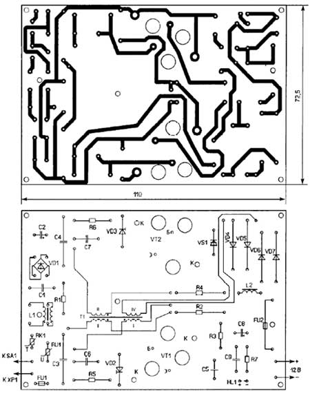
The mains voltage is supplied to the SMPS through a fusible link FU1, which, together with the varistor RU1, protects the SMPS elements from increased mains voltage. Thermistor RK1 limits the current pulse when charging capacitors C2-C4 at the moment the SMPS is turned on. The mains voltage through the noise filter L1C1 is supplied to the diode bridge VD1, where it is rectified and then smoothed by the capacitor C2. Elements C5, R3, VS1 form a circuit that facilitates the start of the converter when it is turned on. Damping diodes VD2, VD3 limit the amplitude of voltage pulses on the collectors of switching transistors VT1, VT2 to a safe value. The heat dissipation in these transistors turned out to be small, so they were used without heat sinks. In the heaviest mode, the transistors heat up to 50°C. Resistors R2, R4 form an OOS circuit for current, and circuits R5C6 and R6C7 are designed for forced switching of transistors. The output alternating voltage rectifies the diode bridge VD4-VD7, L2C8C9 is a smoothing filter, and the inductor provides an inductive filter response, which is necessary for a reliable start of the converter. Installing capacitors with a capacitance of 68 nF or more at the rectifier output will make it impossible to start. LED HL1 indicates the presence of the output voltage. All parts of the SMPS are mounted on a printed circuit board made of one-sided foil fiberglass, the drawing of which is shown in fig. 2.
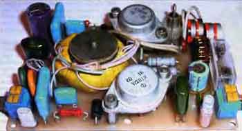
To improve the cooling of transistors, ventilation holes are made in the board under them. Inductor L1 and transformer T1 are fixed with screws. After these screws are inserted into the holes of the board, pieces of a PVC tube should be put on them from the side of the parts. Then they install a choke, a transformer and press them against the board with plastic washers. The transistors are screwed onto metal stands and then soldered to the board. The FU1 fuse consists of two tinned pins pressed into the board, between which a copper wire with a diameter of 0,03 mm is soldered. Outside, it is closed with a piece of PVC tube to protect against mechanical damage, and in case of operation, to protect the components of the SMPS from splashes of molten metal. For the FU2 fusible insert, a metal-plastic holder is mounted on the board. The appearance of the assembled and connected to the network SMPS is shown in fig. 3.
We replace the KN102D dinistor with DB3, DB4 or any of the KN102 series, 1.5KE350CA diodes are replaceable with 1.5KE300CA, 1.5KE400CA, 1.5KE440CA, 2D2999B diodes - with KD2999A, KD213A-KD213V, KD2997A, K D2997B. The YL-BB3N7M LED can be replaced with any small-sized LED of any glow color with an operating current of up to 20 mA. After conducting experiments, the author found out that the KT812A transistors are interchangeable with KT840A. When using transistors 2T704A, KT704B, KT809A, the heating increased, but was within acceptable limits, however, they have a different case, which will require a change in the topology of the printed circuit board. SCK-103NTC thermistor can be replaced with MZ92-P220RM, MZ92-R220RM, MZ92-P330RM, MZ92-R330RM, VCR391 varistor - JVR-10N361K, JVR-14N361K, JVR-20N361K, JVR-10N391K, JVR-14N391K , JVR- 20N391K, JVR-10N431K, JVR-14N431K.JVR-20N431K. Inductor L1 is wound on a M2000NM magnetic circuit of size K10x6x5 and contains 10 turns of MGTF 0,12 or PELSHO 0,3 wire folded in half. The inductor L2 is wound on a M2000NM magnetic circuit of size K16x10x5, the winding contains 24 turns of PETV or PEV-2 wire with a diameter of 0,85 mm. For transformer T1, a magnetic circuit M2000NM-A K32x18x7 made of ferrite was used (the magnetic permeability measured by the author was 1885, and the deep saturation induction was 0,38 T). It is permissible to use M2000NM1, M2000NM1-17, M2000NM-39 magnetic cores of size K32x20x6. For winding, you can use PETV, PEV-2 or PELSHO wire, windings I and III each contain 8 turns of wire with a diameter of 0,3 mm, winding II - 351 turns of wire with a diameter of 0,45 mm, winding IV - 33 turns of wire with a diameter of 0,85 mm. Preliminarily, the edges of the magnetic circuit are grinded and two layers of varnished cloth or one layer of fabric insulating tape are wound. The wires of all windings are laid tightly to the magnetic circuit. Windings I and III are wound first simultaneously in two wires with a gap of 3 ... 5 mm between the wires to prevent breakdown. Then the windings are impregnated with shellac and two layers of varnished fabric are wound. Next - one layer of winding II, laying the wire "coil to coil". There should be a distance of 6 ... 7 mm between the beginning and end of this layer, the wire is fixed and the winding is impregnated with shellac. Next, a layer of varnished cloth is laid and the second and third layers of winding II are wound in the same way, after which two layers of varnished cloth or insulating tape are laid. The winding IV is wound last, impregnated with shellac. Then - two or three layers of insulating tape to protect the windings from mechanical damage. When setting up, it should be remembered that the elements of the SMPS are under life-threatening mains voltage, therefore, all replacement of elements with the device disconnected from the mains. Before connecting the source to the network for the first time, you should check the installation and make sure that the assembled product matches the diagram. After that, the fuse-link FU2 is removed from the holder and the SMPS is connected to the network. If autogeneration does not occur after switching on, then increase the capacitance of the capacitor C5 to 1 μF or install a resistor R3 with a resistance of 120 ohms. If the idling current of the SMPS is more than 40 mA (measured between the network filter and the diode assembly VD1), then this means that the saturation induction of the magnetic circuit is much less than 0,38 T. In this case, it is necessary to proportionally increase the number of turns in all windings of the transformer T1. The number of turns should be increased by at least 10 ... 15%, and if necessary, more. During normal operation of the SMPS, transformer T1 should emit a quiet whistle. In conclusion, it should be noted that the basis of this SMPS is the T1 transformer, therefore, if it is necessary to use a magnetic conductor of a different size or obtain a different power, all elements should be recalculated. The easiest way to do this is on a computer using the author's program Converter 4.0.0.0, moskatov.narod.ru/ Converter.html Author: E. Moskatov, Taganrog, Rostov Region; Publication: cxem.net
Machine for thinning flowers in gardens
02.05.2024 Advanced Infrared Microscope
02.05.2024 Air trap for insects
01.05.2024
▪ Headphones with heart rate sensor ▪ Viruses help the immune system ▪ Lecture Schedule - on E Ink panels
▪ section of the site Experiments in chemistry. Article selection ▪ article Nature does not make leaps. Popular expression ▪ How is heat and cold formed? Detailed answer ▪ article Maintenance of PCM system equipment. Standard instruction on labor protection ▪ article Touch relay. Encyclopedia of radio electronics and electrical engineering
Home page | Library | Articles | Website map | Site Reviews
www.diagram.com.ua |

 Leave your comment on this article: