|
|


 Arabic
 Bengali
 Chinese
 English
 French
 German
 Hebrew
 Hindi
Hindi Italian
 Japanese
 Korean
 Malay
Malay Polish
 Portuguese
 Spanish
 Turkish
 Ukrainian
 Vietnamese
|
ENCYCLOPEDIA OF RADIO ELECTRONICS AND ELECTRICAL ENGINEERING PBX - prefix to the computer. Encyclopedia of radio electronics and electrical engineering
Encyclopedia of radio electronics and electrical engineering / Telephony Modern office automatic telephone exchanges are widely used in organizations and institutions. They allow you to expand the possibilities of telephone communication with a limited number of lines. As a rule, the main element of such stations is a processor or microcontroller. The author of the article suggests using a personal computer instead, since now there is a large amount of computer equipment that is a little outdated, but it may well perform such a not very difficult task as managing an office PBX. The developed automatic telephone exchange is a software and hardware complex based on the IBM PC. The device is connected to the LPT port of a computer equipped with a sound card, an uninterruptible power supply and an operating system (OS) Windows 95/98 or Windows NT4.0/2000/XP (the latter is preferable for reasons of reliability). Naturally, the computer must work constantly. The telephone equipment connected to the PBX can be very diverse: single-line rotary or push-button telephones with tone or pulse dialing, cordless telephones (radio telephones), modems, fax machines, etc. The total number of external and internal lines is 14, the maximum number of simultaneous connections - 5. The maximum possible galvanic isolation is implemented in the PBX: only those sets that are currently connected are galvanically connected. Main functionalities: type="disc">PBX consists of several modules. The main module is shown in fig. 1. It contains an interface on microcircuits DD1 - DD9 for communication with a computer, a power supply for subscriber sets (hereinafter referred to as AK) and connectors XP1, X1-X17. The AC power supply includes a generator on the elements of the DD10 microcircuit, a transistor VT1 and a transformer T1.
The XP1 connector is designed to connect the PBX to the LPT port of the computer, X17 - to the generator unit (see below). KX1-X15 AK, sets of external lines (KVL) and musical set (MK) can be connected. Contacts of the same name 1, 4-25, 28-40 of connectors X1-X15 are interconnected; 2 and 3 - connected to the corresponding outputs of the decoders DD9, DD8; 26 and 27 - to the corresponding rectifiers for supplying +36 V power to the AC. For KVL and MK, this voltage is not needed, therefore it is not supplied to the X13-X15 connectors, and the T1 transformer contains 12, not 15 secondary windings. Connectors X13-X15 are intended for connection only of KVL and MK, and X1-XI2 - for any sets. The corresponding device type must be set in the CTIServer.exe program (to do this, double-click the left mouse button in the "View" column in the corresponding line). A standard power supply from IBM PC AT is connected to the X16 connector. Any other source with an output voltage of +5 V and +12 V at a current of up to 2 A and -5 V at a current of up to 0,25 A can be used. To power the AK, a converter with a frequency of about 20 kHz was assembled on the elements of the DD10 microcircuit. If necessary, the frequency and duty cycle of the pulses can be selected with resistors R33 and R34. For more reliable closing of the transistor VT1 on the pin. 7 DD10 -5 V voltage is applied. Each AC has its own secondary winding of the T1 transformer and its own rectifier. This variant of AC power supply allows to galvanically isolate all ACs and not to use transitional transformers in CVL (as it was done in [1]). The use of transient transformers degrades the quality of the speech signal and adversely affects the speed of data exchange through the modem. Transformer T1 is made on a ring of size K28x22x6 from ferrite M2000, the primary winding contains 24 turns of wire PEV-2 0,5, the secondary - 72 turns of wire PEV-2 0,2 each. Transistor VT1 is installed on a heat sink with an area of 30 cm2. For each connector and microcircuit, it is desirable to connect blocking capacitors in the power circuits (not shown in the diagram). As connectors X1-X15, you can use MPH or ISA, removed from faulty computer motherboards. The interface consists of input buffers DD2, DD7, address latch DD6, signal shaper WAIT DD3, decoder of the address of the data reading mode DD9, decoder of the address of the data writing mode DD8. Buffer DD2 in data reading mode is in a normal state, in all others - in high impedance. A schematic diagram of a subscriber set (AK) is shown in fig. 2. It consists of a current limiter L1R2R3U1.1 (25 mA), a tone dialing receiver DD4, a data latch DD2 with a decoder DD3 and a part of the switching field K1-K7.
Relay K1 is used to supply ringing voltage, K2 - station signal, K3, etc. - to connect to cord sets (SC). By SC we mean a pair of wires through which you can establish a connection for a conversation. The number of relays to connect to the HQ in all sets must be the same and must be equal to the maximum number of simultaneous connections, which is adjusted in the settings\parameters window. It is selected based on the number of internal subscribers and external lines. The design of the subscriber set can be improved by using a current stabilizer on a transistor instead of a limiter (Fig. 3), and also simplified (slightly worsening the quality of dial tone recognition). To do this, exclude the transformer T1 and elements C7, R11, replace the DD1 chip with K561LE5, and connect pin 2 of the DD4 chip to pin 5 of the new DD1 chip through capacitor C6. In this case, the signal will pass through the optocoupler. A tone dialing receiver is generally not required if the CO or telephone set does not support this type of dialing.
Instead of the inductor L1 and optocoupler U1, it is possible to use an electromagnetic relay, for example, RES9 (passport 205). The disadvantages of this option: contact bounce and uncertain operation on long subscriber lines with high resistance and different telephone sets. The tone dialing receiver of the DTMF standard is assembled on the KR1008VZh18 chip, which is described in detail in [4, 5]. As a choke L1, a winding with a magnetic circuit from the RES9 relay (passport 205) is used. The windings of different AKs must be shielded from one another or spaced apart in space, otherwise a conversation from a neighboring SC can be heard. Transformer T1 is made on an armored magnetic circuit B18 x 3 x 10 of M2000 ferrite and contains two windings of 300 turns of PEV wire - 2 0,1. The external line set diagram is shown in fig. 4. Unlike AK, it does not have a tone dialing receiver, there is no relay for supplying ringing voltage and station signal, but there is an incoming call receiver.
Just like in AK, relays K1 - K5 are used to connect to the SC. Their number must be equal to the maximum number of simultaneous connections, and their windings must be connected to the outputs of the decoder, starting from 3. When connecting external lines to the PBX, it is desirable to take into account the polarity in order to avoid loud clicks in the handsets due to the recharging of the isolation capacitors. As a choke L1, windings from the RES9 relay (passport 205) are also used. If necessary, the current in the external line can be selected by resistor R6. The scheme of the musical set is shown in fig. 5. It consists of an isolating transformer T1, a data latch register DD2 without a decoder, which allows you to turn on the sound filling of more than one SC and part of the switching matrix. Music filling is an important component of the PBX, because the person who calls the office where such a PBX is installed, as a rule, does not wait until one internal subscriber consults with another. If the caller at this moment hears silence, then hangs up, as it is difficult for him to understand what happened - either the connection was broken for technical reasons, or the external line is on hold.
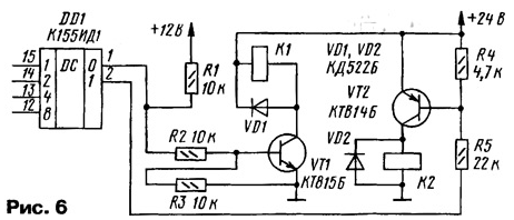
The source of the music signal can be different: sound card, CD-ROM, FM tuner or any external one. The software CD player or media player must be enabled with one or more files looped. If the source of the musical signal does not contain a power amplifier, it must be assembled, for example, on a K174UN14 chip and turned on in front of the T1 transformer. Transformer T1 is made on the B18 x 3 x 10 armored magnetic circuit from M2000 ferrite and contains two windings of 300 turns of PEV-2 0,1 wire. All kits use RES55 relays with an operating voltage of 12 V, but they can be any with the appropriate supply voltage and transistor switches (more cumbersome). When using keys, it is possible to use less expensive K155ID1 decoders (Fig. 6). When connecting a relay without transistors, one should be guided by the parameters of the K555ID10 chip: current - no more than 80 mA, voltage - no more than 15 V [6]. It is possible to use a 5P14 opto-relay [7, 8] (a more expensive option).
The diagram of the generator block is shown in fig. 7. It consists of a ring voltage source and a station signal generator. The RC generator of sinusoidal oscillations with a frequency of 425 Hz is assembled according to the Wien bridge scheme [9]. A master node is assembled on the DA1 chip, a voltage stabilizer on the transistor VT1, and an emitter follower on VT2.
The output impedance of the generator should be as low as possible to prevent the tone dialing signal from getting from one AC to another while they are connected to the generator at the same time. For this, an amplifier on a DA2 chip and a T2 transformer are used. The ringing voltage shaper is made on a T1 network transformer with a VD4-VD7 diode rectifier. It creates an alternating voltage of 60 Veff with a frequency of 50 Hz with a constant component. As T1, a standard transformer TAN 13-220-50K is used. It contains four windings of 30 Veff. Winding II consists of two 30 V windings connected in series, similarly, winding III is composed of two 30 V windings. It is possible to use another transformer with two secondary windings of 60 V eff. 2 turns of wire PEV-18 3. The proposed option for the location of the exchange nodes, where each set is assembled on a separate board with a connector, is not the most successful, but accessible for understanding the operation of the station. The author assembled the PBX on prototyping boards in three blocks placed in a standard IBM PC case: type="disc">The optimal option is where two or four sets are assembled on one board (depending on the dimensions of the relay). In this case, it is necessary to use connectors with a large number of contacts. Now let's move on to the description of the software. Installation. Unzip the ats_pc.zip archive to drive C. The C:\ATS\MIDI directory should contain the music.mid file, which will start playing in a circle when CTIServer.exe is launched. Run reg.bat. If the operating system (OS) Windows95/98/ME is installed on the computer, it is enough to connect the PBX to the parallel port of the PC (when the computer and PBX are turned off) and run CTIServer.exe. First you need to check the LPT port mode: it should be EPP1.7 or EPP1.9. Windows NT4/2000/XP prohibits direct access to ports. It can be bypassed using the PORTTALK.SYS driver. To do this, download the porttalk22.zip archive from [3], unpack it, copy porttalk.sys to the C:\WINNT\SYS-TEM32\DRIVERS directory (for Windows XP - C:\WINDOWS\SYSTEM32\DRIVERS); copy Allowlo.exe to the C:\ATS directory; run ats_winnt.bat instead of CTIServer.exe. Under Windows 2000, the PBX worked for several months without failures. A properly assembled PBX does not need to be adjusted, although when connecting long subscriber lines, you will have to select resistors R2, R3 (see Fig. 2) according to the current in the 25 mA line when the telephone is off-hook. The optocoupler must work confidently. Briefly about the logic of the PBX. Extension 1 picks up the handset, after 0,2 seconds, he will hear the dial tone. After that, he can dial a two-digit number. If this number corresponds to any extension, for example 2, who is in the SLEEP state, then the subscriber 2 is assigned the status RINGJNT, and the subscriber 1 is assigned the status RC (RING CONTROL). At the same time, subscriber 1 hears the ringback control (long beeps), and the telephone set of subscriber 2 receives a ringing signal. If subscriber 2 picks up the handset, a free barcode connection will be established. If subscriber 2 is busy, there is no free barcode, or the dialed number does not match the internal subscriber, subscriber 1 hears short beeps (BUSY status). All current states of the kits can be observed on the monitor screen in the main window of the CTIServer.exe program and read in log files, where they are recorded with timestamps. When an external call arrives, the RINGJEXT state is assigned to extensions according to the list edited in the properties window of this external line. To get to the properties window of a device, double-click the left mouse button in the "View" column in the corresponding line. There are separate lists for day and night operation of the station. If the internal subscriber dialed the number 9, the connection is made with the first free external line from the list stored in the properties window of this subscriber (there are also separate lists for day and night operation modes). In the same window, you can disable long-distance access, enable notification and unconditional seizure of an external line. You can select a specific external line by dialing the number 8 and the serial number of the line in the list. For example, number 82 corresponds to the second line of the list. If "busy" is enabled in the subscriber's properties, then as soon as he picks up the handset, a connection will be made to the external line (ie, you do not need to dial 9). In this case, if he wants to call another internal subscriber, he must dial the * button before the number (ie, for example, not 12, but *12). When priority occupation is enabled, an outside line is connected even if it is busy (the previous connection is disconnected). Dialing another extension is also done using the * button. The tone dialing signal passes to the external line through the isolation capacitors without hindrance, so no additional measures need to be taken. Pulse dialing will not work this way. It is impossible to refuse isolation capacitors, therefore, this function is implemented by the program. If an internal subscriber is in a state of connection with an external line and his loop is interrupted for a time greater than timeO and less than timel, this is regarded as pulse dialing. This pulse is transmitted to the external line by interrupting its loop for a time that is set using the pulseouttime variable in the setup\parameters window. The program also provides for the conversion of tone dialing to pulse dialing. This is necessary if the telephone set is switched on in the tone dialing mode, and the city PBX does not support this mode. If extension 1 is connected to an outside line or another extension 2 and its loop breaks for more than time2 and less than time1, it is regarded as entering the SERVICE mode, which is confirmed by two short beeps. The connection of subscribers 2 and 2 is broken, subscriber 1 starts to hear music. Subscriber 3 can then dial any other extension (eg 3). If subscriber 1 picks up the phone, a connection will be established between subscribers 3 and 2, subscriber 1 continues to listen to music at this time. If subscriber 3 or subscriber 2 hangs up for a time greater than time2, the connection of subscribers 3 and 2 or 1 and 2, respectively, will be established. You don't have to wait until the interlocutor hangs up: if subscriber 3 or 1 breaks his loop for a time greater than time2 and less than time2, then a connection will be established between subscribers 1 and 2 or 3 and XNUMX, respectively. In the settings\parameters window, you can also adjust the duration of the time period after which it is considered that the pulse dialing of a digit is completed (interdigital pause), the duration of the call, its control and the pause between them (RING / RING CONTROL), the duration of the short beep (BUSY). Here you can also set the time for automatic transition from day mode to night mode, and vice versa. If an internal subscriber tried to connect to an outside line, but it was busy, he will hear short beeps. At the same time, if he dials the number 6, the WAIT mode will turn on, which will be confirmed by two short beeps, after which he hangs up. As soon as the outside line becomes free, he will receive the call. For several subscribers with WAIT mode, a queue is formed. The system also allows the "Call Pickup" mode. If subscriber 1 received a call from subscriber 2 or an external line, but he did not answer it, then subscriber 3, having dialed the number 4 and personal number of subscriber 1 on his telephone set, establishes a connection with subscriber 2. Transfer from day mode to night mode, and vice versa, occurs automatically at a specified time or manually from any telephone. To do this, dial 782# or 781# respectively. An analysis of the market for personal computers and office PBXs showed that the PBX models sold (Panasonic, LG, etc.) with the same number of internal subscribers and external lines have a price that exceeds the cost of the described PBX by more than 5 times (excluding the cost of IBM PC). The low requirements of the PBX software to computer resources make it possible to use inexpensive models (P133, 32 MB of RAM, 540 MB of HDD are enough). You can connect the PBX to a dedicated server. PBX software and additional information on the use of the EPP port. When connecting the device to public telephone networks, you must obtain a certificate. Literature
Author: S. Kunitsyn, Kaliningrad
Artificial leather for touch emulation
15.04.2024 Petgugu Global cat litter
15.04.2024 The attractiveness of caring men
14.04.2024
▪ Robotic materials with the properties of living beings ▪ The Pilot headphones translate in real time ▪ Environmentally friendly batteries
▪ section of the site Audio Art. Article selection ▪ article by Marcel Proust. Famous aphorisms ▪ article Alfalfa brazilian. Legends, cultivation, methods of application ▪ article Focus with Chinese coin. Focus Secret
Home page | Library | Articles | Website map | Site Reviews
www.diagram.com.ua |


 Leave your comment on this article: