|
|


 Arabic
 Bengali
 Chinese
 English
 French
 German
 Hebrew
 Hindi
Hindi Italian
 Japanese
 Korean
 Malay
Malay Polish
 Portuguese
 Spanish
 Turkish
 Ukrainian
 Vietnamese
|
ENCYCLOPEDIA OF RADIO ELECTRONICS AND ELECTRICAL ENGINEERING Adjustment of phase inverters. Encyclopedia of radio electronics and electrical engineering
Encyclopedia of radio electronics and electrical engineering / Speakers Radio amateurs engaged in the independent manufacture of phase inverter loudspeakers (hereinafter, for brevity, simply a phase inverter) often encounter the fact that the designs they repeat do not provide the technical characteristics given in the descriptions. This happens due to a significant technological variation in the parameters of low-frequency heads, so each manufactured loudspeaker must be adjusted. When setting up phase inverters, radio amateurs usually use the same technique as when calculating them [1, 2]. As a result, the acoustic losses that occur in a real design, the difference between the equivalent and physical volumes of the box, and a number of other factors affecting the accuracy of tuning are not taken into account. The proposed tuning technique takes into account these factors, so its accuracy is much higher. The tuning of any phase inverter comes down, as is known, to finding a certain combination of the values of its tuning frequency ff and the output impedance of the amplifier Rout, which ensures a smooth frequency response of radiation at low audio frequencies. You can find these values using the relationship that exists between the parameters of the phase inverter and the closed box. If the tunnel hole is closed in a phase inverter with a smooth frequency response, then the total quality factor of the system head - closed box will be equal to 0,6, and the resonant frequency of the head in such a box fr will be related to the tuning frequency of the phase inverter by the dependence ff = 0,61 ... 0,65 fr. The coefficient of proportionality of the indicated values depends on the ratio of the equivalent volume of the head to the useful volume of the box, and if we take it equal to 0,63, then the error in determining the frequency ff will not exceed 5% for any ratio of the indicated volumes encountered in real structures. Setting up a phase inverter should begin with determining the optimal amount of sound-absorbing material placed in it. To do this, closing the tunnel opening (for example, with a plywood circle smeared along the edges with plasticine), select such an amount of material at which the frequency fp is minimal. Then, having fixed the absorbing material on the walls of the box, the resonant frequency of the head-closed box system is measured and, using the ratio ff = 0,63 fp, the frequency of the phase inverter tuning is determined, and then the length of its tunnel:
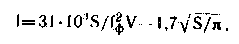
where V is the free volume of the phase inverter box in liters, and S is the opening area of the phase inverter tunnel in sq.cm. Usually, the equivalent volume of acoustic design, when the optimal amount of sound-absorbing material is placed in it, turns out to be greater than the geometric one, so the length of the tunnel has to be reduced when setting up the phase inverter. To determine the corrected value 1', the value of the bass reflex tuning frequency, obtained with the length of the tunnel 1, is substituted into the above formula and the equivalent design volume Ve is found. Then, replacing V with Ve in the same formula, the refined value of the tunnel length 1' is calculated. The output impedance of the amplifier Rout can be found based on the condition under which the quality factor of the system amplifier - closed box takes a value equal to 0,6, however, it is preferable to determine the value of Rout from the condition under which the quality factor of the amplifier - box phase inverter system takes the optimal value equal to 1 ( in this case, the amplifier tuning procedure is simplified and the losses occurring in the inverter tunnel are taken into account).
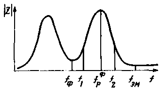
The quality factor of the head-box-phase inverter system is determined by the method adopted for head-closed box systems [1,2], but all the necessary measurements are carried out near the high-frequency resonance frequency of the frequency response of the loudspeaker input impedance fp (see figure). To improve the accuracy of subsequent calculations, the frequency response parameters of the input impedance of the loudspeaker should be measured from the side of the connector for connecting it to the amplifier. In this case, the influence of the active resistance of the connecting wire and the separation filter coil on the loudspeaker parameters is taken into account. Calculating the acoustic quality factor [3]
where Ur is the voltage at the frequency fp, Uem is the voltage at the frequency of the electromechanical resonance fem, f1 and f2 are the cutoff frequencies according to the voltage level U1,2 = root (UrUem), find the electrical and total quality factors of the system:
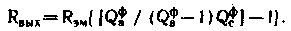
if the found value of Qp differs from unity by no more than 10%, then the frequency response of the phase inverter will be quite smooth when working together with almost any transistor amplifier with low output impedance. If Qp>1,1 (this is the case in amateur radio practice most often), then an amplifier with a negative output impedance should be used to work with a phase inverter. To obtain a smooth frequency response of the loudspeaker radiation, it is necessary to adjust the feedback circuit that forms the negative output impedance of the amplifier [4]. To do this, pre-determine the damping coefficient Kd = Qp / Qp.opt, which shows how many times it is necessary to reduce the total quality factor of the head - box-phase inverter system in order to obtain optimal damping. Since the condition for optimal damping of the phase inverter assumes Qp.opt=1, then Kd=Qp. Further, by connecting the loudspeaker to the amplifier and applying the last sound signal with a frequency fem, the bridge of the feedback circuit is balanced and the voltage at the amplifier output is measured. Then, by rebuilding the generator to the frequency fp and changing the transfer coefficient of the feedback circuit, they achieve a decrease in the voltage at the output of the amplifier by a factor of Kd. As a result of this setting, exactly the value of the output impedance of the amplifier is set, at which a smooth frequency response of the loudspeaker radiation at low frequencies is obtained. When calculating a power amplifier, it is desirable to determine the required output impedance in advance. It is calculated according to the formula
The above procedure, without any changes, is also applicable to setting up loudspeakers in which dual or several heads of the same type are installed. Literature
Author: V. Zhbanov, Kovrov, Vladimir Region; Publication: N. Bolshakov, rf.atnn.ru
Artificial leather for touch emulation
15.04.2024 Petgugu Global cat litter
15.04.2024 The attractiveness of caring men
14.04.2024
▪ The most powerful solar power plant launched ▪ SHARP DV-HRW30 - VHS VCR, DVD and HDD recorder ▪ REM sleep warms up the brain and saves from hypothermia
▪ site section Chargers, accumulators, batteries. Article selection ▪ toilet article. History of invention and production ▪ article What role did dogs play in conquering the South Pole? Detailed answer ▪ article Fenugreek hay. Legends, cultivation, methods of application ▪ article CD-ROM based CD player. Encyclopedia of radio electronics and electrical engineering
Home page | Library | Articles | Website map | Site Reviews
www.diagram.com.ua |


 Leave your comment on this article: