|
|
ENCYCLOPEDIA OF RADIO ELECTRONICS AND ELECTRICAL ENGINEERING Tone generator for EMP. Encyclopedia of radio electronics and electrical engineering
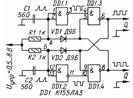
Encyclopedia of radio electronics and electrical engineering / Musician Multi-voice EMPs with a single tone generator have already proven to be reliable and practical devices. However, their capabilities are often not fully realized due to the peculiarities of the generators used in them. As a rule, a tone generator is built on the basis of a highly stable quartz resonator or RC circuits. In this case, electronic frequency control is either excluded or extremely difficult [1]. The device described below is a voltage controlled tone generator. The control signal is taken from various drivers and EMP controls. These can be frequency vibrato generators, envelope generators (for automatic tuning change), glissando regulators (tuning slip) with manual or foot (pedal) control. The features of the generator include a high operating frequency. The use of a digital microcircuit made it possible to implement a relatively simple and cheap VCO with an operating frequency up to 7,5 ... 8 MHz (Fig. 1). For most digital tone generators with an equal-tempered musical scale, usually consisting of 12 identical counters with different interval conversion factors, a clock (leading) frequency within 1 ... 4 MHz is required. Therefore, the characteristics of the generator must be such as to provide the necessary linearity within these frequency limits.
The principle of operation of the generator is based on the formation of pulses regulated in duration by two identical voltage-controlled shapers closed in a ring. Thus, the decay of the pulse at the output of one shaper causes the appearance of the front of the next pulse at the output of another, and so on. The operation of the device is illustrated by the timing diagrams shown in fig. 2.
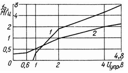
Until the moment t0, the control voltage is zero. This means that at points A and B a signal with a logical 0 level has been established, since the outflowing input current of the elements DD1.1 and DD1.2 (it does not exceed approximately 1,6 mA) is closed to a common wire through resistors R1 and R2 and a small output control voltage source resistance. The output of the inverters DD1.1 and DD1.2 at this time is level 1, so the RS-trigger on the elements DD1.3 and DD1.4 will be set arbitrarily in one of the stable states. Assume for definiteness that the direct (upper according to the scheme) output has a signal of 1, and the inverse one has a signal of 0. When a certain positive voltage appears at the control input at the moment t0, a current will flow through the resistors R1 and R2. In this case, at point A, the voltage will remain close to zero, since the current through the resistor R1 flows to the common wire through the low resistance of the VD1 diode and the output circuit of the DD1.4 element. At point B, the voltage will rise, since the diode VD2 is closed by a high level from the output of element DD1.3. The current through the resistor R2 will charge the capacitor C2 to 1,1 ... 1,4 V in a time depending on its capacitance, the resistance of the resistor R2 and the value of the control voltage. Increasing Uynp increases the charging rate of the capacitor and it charges to the same level in less time. As soon as the voltage at point B reaches the switching threshold of the element DD1.2, its output will be set to level 0, which will switch the RS flip-flop. Now the direct output will be level 0, and the inverse output will be 1. This will lead to a rapid discharge of the capacitor C2 and a decrease in voltage, and the capacitor C1 will begin to charge. As a result, the trigger will switch again and the whole cycle will repeat. An increase in the control voltage (time period t1...t2, Fig. 2) leads to an increase in the charging current of the capacitors and a decrease in the oscillation period. This is how the oscillation frequency of the generator is controlled. The resulting input current of the TTL elements is added to the current of the control voltage source, which allows you to expand the limits of the control signal, since with a high resistance of resistors R1 and R2, generation can be maintained even at Uynp=0. However, this current is characterized by temperature instability, which affects the stability of the generation frequency. To some extent, it is possible to increase the temperature stability of the generator by using capacitors C1 and C2 with a positive TKE, which will compensate for the increase in the uncontrolled outflowing input current of the elements DD1.1 and DD1.2 when the temperature changes. The oscillation period depends not only on the resistance of the resistors R1 and R2 and the capacitance of the capacitors C1 and C2, but also on many other factors, so an accurate assessment of the period is difficult. If we neglect the time delays of the signals in the elements DD1.1-DD1.4 and take the value of their logic voltage 0, as well as the threshold voltage of the diodes VD1 and VD2 equal to zero, then the operation of the generator can be described by the expression: T0=2t0=2RC*ln((IеR +Ucontrol)/(IеR+Ucontrol-Usp)), obtained on the basis of solving the differential equation: dUc/dt = Ie/C + (Uupr-Us)/(RC), where R and C are the ratings of the timing circuits; Uc - voltage across capacitor C; Usp - maximum (threshold) value of voltage Uc; Uynp - control voltage; Ie - the average value of the input leakage current of the TTL element; t0 - pulse duration; T0 - oscillation period. Calculations show that the first of these formulas agrees very precisely with the experimental data at Uynp>=Usp, while the average values were chosen: Ie=1,4 mA; Usp = 1,2 V. In addition, based on the analysis of the same differential equation, we can conclude that (IеR+Ucontrol)/(IеR+Ucontrol-Usp)>0, i.e., if IеR/(IеR-Usp)>0, then the device is operational when Uynp≥0; This conclusion is confirmed by the experimental verification of the device. Nevertheless, the greatest stability and accuracy of VCO operation can be achieved with Ucontrol ≥ Usp = 1,2..1,4 V, i.e., in the frequency range of 0,7...4 MHz. A practical circuit of a tone generator for polyphonic EMR or EMC is shown in fig. 3. Operating frequency limits (at Ucontrol ≥ 0,55...8 V) - 0,3...4,8 MHz. The non-linearity of the control characteristic (at a frequency within 0,3 ... 4 MHz) does not exceed 5%. Input 1 is fed a signal from an envelope generator for automatic control of the sound frequency slip. With an insignificant depth of modulation (5 ... 30% of the tone), an imitation of the shades of the sound of a bass guitar, as well as other plucked and percussion instruments, is achieved, in which the height of the intonation of sounds at the time of their extraction deviates slightly from the norm (usually it rises abruptly during the attack of the sound and then rapidly decreases to its normal value). Input 2 is supplied with a constant control voltage from a manual or pedal glissando controller. This input just serves to adjust or change (transpose) the key within two octaves, as well as to slide along the pitch of chords or tonal sounds that imitate, for example, the timbre of a clarinet, trombone or voice. Input 3 is fed from a vibrato generator with a sinusoidal, triangular or sawtooth signal. The variable resistor R4 regulates the level of vibrato within 0 ... + -0,5 tones, as well as the level of frequency deviation up to + -1 octave or more when the SA1 switch is closed. With a high modulation frequency (5 ... 11) Hz) and a depth of + -0,5 ... 1,5 octaves, tonal sounds lose their musical qualities and acquire the character of a noise signal resembling a dull roar or rustling of fan blades. With a low frequency (0,1...1 Hz) and the same depth, a very colorful and expressive effect is achieved, similar to the "floating" sound of a ukulele. The signal from the output of the tone generator must be fed to the input of the digital shaper of the equal-tempered musical scale signals. An active adder of control signals is assembled on the operational amplifier DA1. The signal from the output of the adder is fed to the input of the VCO, which is made on the logic elements DD1.1-DD1.4. In addition to the VCO, the device contains an exemplary quartz oscillator assembled on the elements DD2.1, DD2.2, as well as a circuit of two octave frequency dividers on the triggers of the DD3 microcircuit. clocked by this generator. The generator and triggers form three exemplary signals with a frequency of 500 kHz, 1 and 2 MHz. These three signals and the signal from the VCO output are fed to the input of electronic switches assembled on open-collector elements DD4.1-DD4.4. These switches, controlled by switches SA2-SA5, have a common load - resistor R13. The output circuits of the elements form a device with a logical OR function. When one of the switches passes its clock signal to the output, the rest are closed low from the switches. A high level for applying to the R-inputs of the D-flip-flops DD3.1 and DD3.2 and to the contacts of the switches SA2-SA5 is removed from the output of the element DD2.4. A quartz oscillator with frequency dividers play an auxiliary role and serve mainly for the operational adjustment of the VCO or "lead" the instrument in the "Organ" mode, while the switches SA3, SA4, SA5 ("4'", "8'", "16'" ) allow you to shift the EMP system, respectively, from the lowest register by one and two octaves up. In this case, of course, there can be no adjustment or change in the pitch of sounds. The disadvantages of the generator include a relatively low temperature stability, which in this case is not of great importance [2], and a significant nonlinearity of the control characteristic of the VCO at the edges of the range, especially in the lower frequencies of the operating range of the generator. On fig. 4 shows the experimentally taken dependence of the generation frequency on the control voltage: 1 - for the generator according to the circuit of fig. 1, 2 - fig. 3.
The device is assembled on a printed circuit board made of foil fiberglass with a thickness of 1,5 mm. Chips of the K155 series can be replaced with similar ones from the K130 and K133 series; K553UD1A - on K553UD1V, K553UD2, K153UD1A, K153UD1V, K153UD2. Instead of D9B, you can use diodes of this series with any letter index, as well as D2V, D18, D311, GD511A. Capacitors C4 and C5 are better to choose with a positive TKE, for example. KT-P210. KPM-P120, KPM-P33, KS-P33, KM-P33, K10-17-P33, K21U-2-P210, K21U-3-P33. Capacitors C7, C10, C11 - K50-6. Particular attention should be paid to careful shielding of the device. The output conductors must be twisted into a cord with a pitch of 10..30 mm. A properly mounted tone generator does not need adjustment and starts working immediately after the power is connected. The control voltage at the VCO input should not exceed 8 ... 8,2 V. The frequency stability of the generator is adversely affected by changes in the supply voltage of 5 V, so it must be powered from a source with a high stabilization factor. Literature
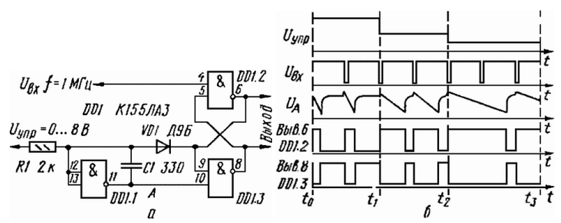
Author: I.Baskov, village of Poloska, Kalinin region Addition A simple, voltage-controlled generator, described in the article by I. Baskov "Tonal generator for EMP" ("Radio", 1987, No. 5, p. 48-50), when repeated, turned out to have significant drawbacks: significant nonlinearity of the control characteristic, large frequency dependence fluctuations from the supply voltage of the microcircuit and from the ambient temperature. The main drawback is that the generator is poorly excited. This happens due to the fact that when the power is turned on, a high level voltage can simultaneously occur at the inputs of the elements DD1.1 and DD1.2 (see Fig. 1 of the named article), and a low voltage can appear at their outputs. The low-level voltage at the inputs of the RS flip-flop, assembled on elements DD1.3 and DD1.4, sets and holds the trigger in such a state when its direct (pin 6) and inverse (pin 8) outputs are high, at which the generator does not excited. This drawback can be eliminated by including elements DD1.1 and DD1.2 also according to the RS flip-flop circuit. Then, at the inputs of these elements, a high-level voltage cannot be established at the same time and the generator is easily excited. A diagram of a generator with the best characteristics is shown in fig. 1, a. Elements DD1.1 and DD1.2, included RS-flip-flop, together with capacitors C1 and C2 are generators of linearly varying voltage with capacitive feedback. Thanks to the feedback through the capacitors C1 and C2, the control characteristic is linear over the entire range of generated oscillations. Feedback also reduces the dependence of the frequency on the voltage of the microcircuit and on the ambient temperature.
Timing diagrams illustrating the operation of such a generator are shown in Fig. 1b. After the power is turned on, the RS flip-flop on the elements DD1.3 and DD1.4 will be set arbitrarily to one of the stable states. Suppose, for example, that a high-level signal has been established at its direct output, and a low-level signal at its inverse. Consequently, only the capacitor C2 gets the opportunity to charge, and a linearly decreasing voltage is formed at the output of the element DD1.2 (Uv in Fig. 1, b). When the voltage at point B of the generator reaches the switching threshold of the element DD1.4, the RS flip-flop will switch to another stable state. Now, at its direct output there will be a low-level signal, and at the inverse - high, and the capacitor C2 is quickly discharged through the VD2 diode and the DD1.3 element. Similarly, the capacitor C1 is charged. As a result, the RS flip-flop will switch to its original state and the whole cycle will repeat. A change in the control voltage leads to a change in the charging current of the generator capacitors and the period of its oscillations. This is how the oscillation frequency of the generator is controlled. When the control voltage changes from 0 to 8 V (R1 \u2d R2 \u1d 2 kOhm; C150 \u0,25d C4 \uXNUMXd XNUMX pF), the oscillation frequency will be within XNUMX ... XNUMX MHz. If instead of the control voltage Ucontrol, resistors R1 and R2 are supplied with a supply voltage of the microcircuit, then a generator will be obtained, in which rectangular pulses are formed at the direct and inverse outputs, and at the outputs of the elements DD1.1 and DD1.2 - a linearly changing voltage with a small coefficient of nonlinearity ( UA and UB in Fig. 1b). The minimum dependence of the frequency on the supply voltage of the microcircuit will be obtained if the resistance of the resistors R1 and R2 is about 2 kOhm. When the supply voltage changes by + -5%, the frequency changes by + -0,1%. Temperature instability - about 0,05% / ° C. The proposed method for controlling the frequency (period) of oscillations of the generator can be used to control the duration of the pulses. On fig. 2, a is a diagram of a waiting multivibrator, the duration of the output pulses of which is regulated by changing the control voltage Ucontrol. The device works as follows. In the initial state, the direct output of the RS flip-flop has a low voltage, and the inverse one has a high voltage. Trigger pulses, which are low-level signals, switch the RS flip-flop to a stable single state. Capacitor C1 is charging. A linearly decreasing voltage is formed at the output of the DD1.1 element. When it reaches the switching threshold of the element DD1.3, the RS-flip-flop takes the initial state.
A distinctive feature of this multivibrator is the possibility of generating pulses whose duration is greater than the period of the input pulses (t2 - t3 in Fig. 2b). The duration of the output pulses depends on the resistance of the resistor R1, the capacitance of the capacitor C1 and the value of the control voltage. When the control voltage changes from 0 to 8 V (R1 = 2 kOhm; C1 = 330 pF), the duration of the output pulses changes within 5 ... 0,2 μs. The generator and multivibrator described here can be used in voltage converters, measuring instruments, EMI and many other radio engineering devices. Author: A.Ignatenko, Yekaterinburg
Artificial leather for touch emulation
15.04.2024 Petgugu Global cat litter
15.04.2024 The attractiveness of caring men
14.04.2024
▪ 3,5mm battery for wearable electronics ▪ MG4100 Subminiature GPS System
▪ section of the site Life of remarkable physicists. Article selection ▪ article Environmental legislation. Basics of safe life ▪ article Which animals do Finnish farmers cover with reflective paint? Detailed answer ▪ article Sugar beet. Legends, cultivation, methods of application ▪ article Boiling glass in hands. Focus Secret
Home page | Library | Articles | Website map | Site Reviews www.diagram.com.ua |


 Arabic
 Bengali
 Chinese
 English
 French
 German
 Hebrew
 Hindi
Hindi Italian
 Japanese
 Korean
 Malay
Malay Polish
 Portuguese
 Spanish
 Turkish
 Ukrainian
 Vietnamese


 Leave your comment on this article: