|
|


 Arabic
 Bengali
 Chinese
 English
 French
 German
 Hebrew
 Hindi
Hindi Italian
 Japanese
 Korean
 Malay
Malay Polish
 Portuguese
 Spanish
 Turkish
 Ukrainian
 Vietnamese
|
ENCYCLOPEDIA OF RADIO ELECTRONICS AND ELECTRICAL ENGINEERING Assembly and dismantling of elements. Encyclopedia of radio electronics and electrical engineering
Encyclopedia of radio electronics and electrical engineering / Ham Radio Technologies 7.1. Mounting on printed circuit boards.Before installation, printed conductors and contact pads must be prepared for soldering - cleaned of oxide film and dirt. If the installation is carried out immediately after the manufacture of the printed circuit board, then it is enough to wipe the conductors with a calico swab dipped in alcohol. If a lot of time has passed since the manufacture of the board and the metal coating has darkened (oxidized), then first it is necessary to clean it to a shine with a fine-grained sandpaper, and then rinse it thoroughly with alcohol. After degreasing, a thin layer of rosin flux is applied to all contact pads of the printed circuit board with a brush (see Table 9.2). Radio elements and microcircuits also need to be prepared for installation and soldering. To do this, their conclusions are molded (give them the desired shape), cut to the required length, cleaned (clause 7.9) and tinned. Forming the leads is done in order, firstly, to match the distances between them and the pads, and secondly, to prevent peeling of the printed conductors and pads when carelessly pressing the element body. Shaping can be done with tweezers, miniature pliers, round nose pliers or a simple device (section 5.4). Since the adhesion strength of the foil to the board is low and decreases when heated, then when soldering joints on a printed circuit board, care must be taken not to overheat, as this can lead to peeling of conductors and pads from the board. For soldering, solder with a low melting point should be used: POSK 50, POS 61 and others (see Table 9.1). The power of an electric soldering iron when soldering with these solders should not exceed 35-40 W. In some cases, caps are installed in the holes of printed circuit boards for tuning elements. The soldering of the caps is a prerequisite for the reliable operation of the device.
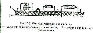
7.2. Compound mounting methodis as follows (Fig. 7.1). At the bottom of the mold corresponding to the dimensions of the future board, a layer of plastic mass (molding clay or plasticine) is placed; a sketch of the wiring diagram is applied on top, made on tracing paper on a scale of 1: 1, indicating the locations of the elements and their conclusions. The sketch is covered with a transparent protective layer, such as plastic wrap. Next, arrange the elements in accordance with the sketch. At the same time, the protective layer, tracing paper and plastic mass are pierced with conclusions. After that, the form is filled with a compound. The conclusions of the radioelements before installing them in the plastic mass are straightened, bent according to the installation sketch, and, if necessary, shortened. The principle of layout of circuit elements is the same as in conventional installation. In the experimental samples of circuit boards, the circuit elements are arranged in such a way that after pouring the case they are above the compound layer. In the worked out circuits, the bodies of the elements can be partially or completely immersed in the compound. Ferrite parts without special protection are not recommended to be poured with a compound. For installation in this way, epoxy, polyester acrylate and similar compounds can be used. The compound should be transparent and easily flowable, and after hardening, elastic. These requirements are met by an epoxy compound of the following composition (in mass parts): epoxy resin-100, dibutyl phthalate from 20 to 25, polyethylenepolyamine from 12 to 15.
The thickness of the compound layer can be 1,5-3,5 mm. The compound polymerizes first at room temperature for 6-12 hours, and after being removed from the mold at a temperature of 60-80 ° C for another 4-6 hours. as well as impact resistance. The electrical resistance of the insulation between the leads of the parts is obtained at least 1000 MΩ. Electrical connections are made with a mounting wire using soldering. If it is necessary to replace the elements, it is enough to heat the leads with a soldering iron to melt the solder and soften the epoxy compound near the leads over the entire thickness of the layer, then remove the element with tweezers or a metal hook, insert a new one in its place and fill it with compound. A fully developed and tuned circuit, if it is intended for operation in conditions of high humidity, it is advisable to implement it in the form of a module, i.e. completely fill with compound both on the side of the element housings and on the mounting side. 7.3. Push-in installationin thermoplastic material (viniplast, organic glass, etc.). The conclusions of all elements before installation on the board are formed, as shown in Fig. 7.2. During installation, they are pressed against the board with a sharpened soldering iron. In this case, the material of the board melts and the lead is immersed in the board to a depth slightly greater than its diameter. The soldering iron is then retracted and the element held in place until the plastic hardens. The conclusions of the elements that must be connected to each other must be fixed as close as possible to one another and soldered. When soldering, the fastening of the elements is not disturbed, since during the heating of the leads there are practically no mechanical loads on them and the leads are quite well held by the plastic that envelops them. With this installation, it is convenient to use two soldering irons: one to press in parts, the other to bark connections. The assembled and tested board is covered with a protective layer of epoxy glue. 7.4. Installation of homemade modules.The design and assembly of small-sized devices, especially those designed for manufacturing in several copies (equipment for the national economy, for remote control of models, etc.), is greatly simplified when using modules that are complete functional units. The node is preliminarily mocked up, ensuring that it is operational without any additional adjustment when it is assembled from serviceable standard elements with a given parameter tolerance. Then they check the stability of the node operation with the arrangement of elements as it will be in the module. Each element is wrapped with two or three layers of varnished cloth or a piece of polyvinyl chloride tube is put on the body and placed in a clip (Fig. 7.3). Elements that have an annular protrusion on the body (for example, zener diodes) are aligned in diameter by winding varnished cloth. I stack transistors in a round case in pairs with conclusions in opposite directions. The clip clamp with pins moves under the action of a steel spring in the guide grooves and fixes the position of the elements during module installation. The body of the clip is made of sheet steel with a thickness of 0,5 mm. The dimensions indicated in the figure are indicative. Size A is determined by the volume of the module. The elements are mounted by soldering, the entire block is insulated with varnished cloth and placed in a screen-case, which is made of sheet brass or copper with a thickness of 0,2-0,3 mm. The module is filled with an epoxy compound or covered with an insulating plate with holes through which the leads are passed. A module made in this way and containing, for example, two KT316 transistors, five MLT-0,125 resistors and three KM-5a capacitors has dimensions of 12X14X15 mm.
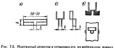
7.5. Wrapping installationwhen prototyping, it allows you to better save the elements, as it eliminates repeated soldering of their conclusions. The essence of the winding installation is that all connections in the device are made with copper bare (preferably tinned) wire, tightly winding it around the leads of the parts. A simple device (Fig. 7.4) allows you to provide reliable electrical contact in the connection and facilitate this operation. The basis of the device is the lead holder cartridge from the drawing compass (a holder with a through axial hole is suitable). A brass tube about 80 mm long is pressed onto the holder shank. Two brass strips measuring 25X5X0,5 mm with mounting holes are soldered to the upper (according to the figure) end of the tube. These strips form a coil holder with a supply of mounting wire; the axis of the coil is a screw. Two steel tubes cut from the needles of a medical syringe are clamped into the cartridge of the lead holder. Tube 1 has an outer diameter of 0,8 and a length of 35 mm, while tube 2 has an outer diameter of 1,2 and 25 mm, respectively. Tube 2 serves as a guide for the mounting wire and at the same time as a cutter that removes the oxide film from it. The protruding end of this tube must be sharpened perpendicular to its axis on the grinding wheel; edges should be sharp but free of burrs. The edges of the opposite end of the tube are smoothed and a guide tube about 100 mm long made of polyvinyl chloride is put on it. Tube 1 is, as it were, an axis: it is put on the output of the part and the device is rotated around it, pressing the end of the mounting wire with a finger to the board. In this case, the mounting wire is pulled out of the tube 2 and tightly wound onto the output. Tube 1 should protrude 4 mm from the cartridge, and tube 2 should protrude 3,7 mm. After winding the wire on one terminal, the device is transferred to another terminal and so, without breaking the wires, the required number of terminals are connected. The required wire tension is set with the screw nut. After a little practice with the device, a fairly reliable electrical contact is obtained. 7.6. Mounting strips, on which the petals are fixed without flaring or riveting, are simple in design and easy to manufacture. The mounting lug blank is cut out of copper or brass foil or tinplate (Fig. 7.5, a). Make cuts on both sides. The "antennae" of the petals are bent (Fig. 7.5,6). Then the workpiece is inserted into the hole and the bar is crimped, as shown in Fig. 7.5, c.
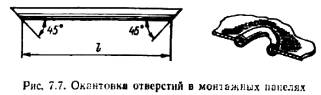
7.7. Clamp for temporary connections conductors and radio elements is convenient when working out simple circuits, as it allows you to quickly connect the leads of various elements or the ends of the mounting wires (Fig. 7.6). A wire clip is inserted into the hole in the circuit board, on which a spring is put on. Stripped mounting wires or element leads are threaded into the loop that protrudes on the front side of the board. By the force of the spring, they will be pressed against one another, providing reliable electrical contact. 7.8. Insulation of radioelement casesduring installation, it can be done with a piece of PVC pipe. For better fixation, the tube in diameter should be chosen slightly smaller than the element body. A piece of tube 1,2-1,5 times longer than the body length is kept in acetone for about an hour (or 30-40 minutes in dichloroethane). After this time, the tube material swells, acquiring exceptionally high elasticity, the tube lengthens and increases in diameter. Using tweezers, the tube is carefully put on the body of the element and kept in the open air for at least 2 hours. During this time, the tube shrinks, tightly fitting the body. Cut off excess tubing. 7.9. Cleaning up conclusions.During storage, the conclusions of radioelements after a while are usually covered with an oxide film, which makes mounting soldering difficult. It is convenient (and fast) to clean the conclusions with the help of a student's ink eraser. Several holes are drilled in the elastic band with a thin drill, through which the wire leads of the elements are pulled 3-4 times with force, squeezing the elastic band with your fingers. Flat leads are pulled between two tightly compressed rubber bands or through a slot made in the elastic band, or the rubber band is used, as usual when erasing, placing the element's lead on a flat surface. 7.10. Mounting piston made of MLT resistor.At a faulty resistor, the cap is carefully separated from the ceramic base with pliers and tinned from the inside, the cap output is soldered into the board hole, and then the parts are inserted into the resulting piston. This method is most effective in the repair of devices, their refinement and improvement. 7.11. Mounting piston from the writing unit of a ballpoint penpractically does not require modification before installation on the board. Its cavity is cleaned of the remnants of the writing paste, calcined on fire and washed with alcohol or acetone. Then they tin the place of future soldering. The piston is installed on the printed circuit board and the junction with the printed conductor is soldered. The excess part of the rod (together with the ball) is cut off. If necessary, the piston glass can be drilled to a diameter of 1,5 mm. 7.12. Spirals instead of pistonsused with a large number of soldered conductors, when there are no ready-made mounting caps of the required diameter and length or material for their manufacture. From the tinned mounting wire, a coil is wound coil to coil on a metal pin of a suitable diameter, a segment of the required length is separated with wire cutters, inserted into the hole in the circuit board and the junction with the printed conductor is soldered. 7.13. Pads for installing transistors of the MP seriescan be made from plastic caps from tubes, for example, from toothpaste. This fastening of transistors provides sufficient rigidity when the device is operating under conditions of shaking and vibration. For the transistor leads, three holes are drilled in the cap. 7.14. Hole trim, through which mounting wires or bundles are passed, can be made using a piece of PVC tube. For edging holes in panels with a thickness of 1-2 mm, you can use a tube with a diameter of 3-5 mm. The length of the segment is determined by the formula l=n(d-0,6), where d is the diameter of the hole; 0,6 is twice the tube wall thickness. The tube is cut at both ends at an angle of 45 ° (Fig. 7.7). With a safety razor or a sharp knife, the tube is carefully cut along the longest generatrix, the edges are pushed apart and the hole is framed. When edging holes in panels with a thickness of 3-7 mm, tubes with a diameter of 7-15 mm are used. 7.15. Dismantling of multi-contact elements(loop coils, transformers, electromagnetic relays, transistors, etc.) is not only laborious, but also does not exclude the possibility of tearing off the foil from the board, since in amateur practice they usually alternately heat the soldering points and, tilting the part, gradually pull the leads of the elements out of the board holes . Below are three ways that are free from these shortcomings.
1 th way.A special nozzle is made on the rod of an electric soldering iron, similar, for example, to those shown in Fig. 8.5, e and 8,8. 2 th way.Solder each output separately, using a device in the form of a tube made of metal that is poorly tinned, for example, aluminum. The wall thickness of the tube should be no more than 0,2 mm, i.e. no more than the gap between the output and the hole in the board. The inner diameter must match the diameter of the soldered lead. The device can also be made from sheet material or from a thin-walled tube of a larger diameter by inserting a wire or a drill shank into it with a diameter equal to the diameter of the outlet. Compress the end of the tube to a length of 5-10 mm with pliers. Excess material should be cut off with scissors and the edge should be filed with a needle file. It is necessary to fix the manufactured tube on a rod made of a heat-resistant material with low thermal conductivity. To solder the output, you need to put a tube on it and heat the place of soldering and the tube with a soldering iron. As soon as the solder begins to melt, the tube, rotating, is inserted into the gap between the lead and the hole, and the soldering iron is removed. After the solder solidifies, the tube is carefully removed. This operation is done with all the conclusions. Then the element can be easily removed from the board without damaging the foil. For the same purpose, you can use a needle from a medical syringe. The tip of a needle of suitable diameter is ground perpendicular to the axis. The burrs must be removed and the hole slightly countersinked from the end. 3 method. The molten solder is sucked out during the dismantling of multi-contact elements using a conventional vacuum cleaner, attaching a thin-walled metal tube with a diameter of 5-8 and a length of 100-150 mm to its flexible hose (p. 5.45). The soldering point is heated with a soldering iron. As soon as the solder begins to melt, a tube is brought to it, and the place of soldering is cleared of solder. While moving through the tube, the drops of solder have time to cool down and do not spoil the vacuum cleaner hose and the dust collector bag. 7.16. Dismantling of microcircuits(for example, the K133 series) it is convenient to produce by inserting a piece of a blade from a safety razor under the microcircuit housing so that the cutting edge rests against the soldering points of two or three extreme leads. By simultaneously heating these soldering irons with a soldering iron, the blade is displaced with force in the direction of the following conclusions. In this case, the blade will separate the leads from the board. Having unsoldered one row of conclusions in this way, proceed to another row. Microcircuits with pin leads can be dismantled by the methods given in paragraph 7.15. 7.17. Grip for dismantling microcircuitsallows you to quickly remove the chip, which reduces the likelihood of overheating. In this case, heating is carried out with a special group soldering iron or nozzle, heating all the leads at once (Fig. 8.5, 8.8). The grip is made from a crocodile clip. On the jaws of the clamp, the teeth are sawn off, two holes are drilled, steel plates 7 mm wide and 1 mm thick are riveted, then their ends are bent at an angle of 90 ° towards one another. The grip ends are inserted under the microcircuit case from the ends, the soldering is heated up and the microcircuit is quickly removed from the board holes (or removed from the contact pads). If the microcircuits are installed on the board tightly one to the other, so that the end grip cannot be installed, it is possible to make a side grip with plates of a slightly different shape. The width of the working part of the plates must be equal to the length of the microcircuit body. Slots are made at the ends of the plates with a width and pitch, like those of the microcircuit pins. Did you know?. 7.18.Checking all radio elements before installation guarantees the operability and successful configuration of the device. Most radio elements can be checked with a conventional tester, and capacitors, including those of small capacity (tens and even units of picofarads), in the absence of a capacitance meter, using headphones. A capacitor charged from a voltage source is discharged to the resistance of telephones and the suitability is judged by the click of the telephone. The larger the capacitance of the capacitor (at a constant voltage), the louder the sound of the discharge will be. With such a check, it is necessary to apply a voltage not higher than the commemorative one for this type of capacitor. 7.19.When it is not possible to replace one or another microcircuit with an identical one, but there is a suitable one in terms of functionality and parameters in another case, you can make an adapter block from foil fiberglass or getinaks. The microcircuit is mounted on an adapter block, which is connected by contact posts to the printed circuit board. Contact racks are made from pieces of wire with a diameter of 0,4-0,5 mm. 7.20. If mounting clips are not installed in the finished board, but they are not at hand and there is no way to follow the advice of paragraphs. 7.10-7.12, then, in order to preserve the printed wiring when selecting elements, pieces of tinned copper wire with a diameter of 0,5-0,6 mm are soldered at the necessary mounting points, and the elements to be selected are soldered to them. At the end of the adjustment, the pieces of wire are removed and the selected element is soldered. 7.21.You can dismantle the microcircuit with pins by carefully heating the printed circuit board from the soldering side in the flame of an alcohol lamp. 7.22.It is convenient to remove the insulation from the mounting wires with a special knife, which can be made from a fragment of a hacksaw blade. The canvas must be released (p. 1.3), drill a hole in it with a diameter of 2-4 mm. Connect the hole to the edge of the canvas with a triangular cutout, sharpen the edges of the cutout. Then harden the canvas. Wrap the handle with insulating tape - and the knife is ready to go. 7.23.Ink for writing on PVC tubes can be prepared by dissolving 6 g of nigrosine in 50 ml of ethanol and adding 50 ml of cyclohexane. 7.24. Silver terminals of radioelements, contact plates, pads can be cleaned of an oxide film, for example, with a 2-5% hydrochloric acid solution for a minute at 50-GO ° C, immersed in a solution or repeatedly wiped with a swab wetted in a warm solution. Then rinse thoroughly and dry. 7.25.If the paint-filled screw is well heated with a soldering iron before unscrewing, the paint will soften and the slot will not be damaged by a screwdriver. 7.26.It is useful to coat the screws of the fastening elements of antennas or other devices located in the open air with a mixture of graphite with machine oil or special graphite grease before assembly. After such treatment, they are easily unscrewed even after several years. 7.27.You can unscrew rusted bolts and nuts if you first douse the connection with kerosene or turpentine (or immerse it in one of the indicated liquids) and set it on fire after some time. After combustion of liquid residues, the threaded connection, as a rule, lends itself to the key. 7.28.A rusted nut with an M8 thread (or more) can be unscrewed if notches 1-2 mm deep are made on one or three faces with a chisel and the thread is moistened with kerosene. Author: tolik777 (aka Viper); Publication: cxem.net
Artificial leather for touch emulation
15.04.2024 Petgugu Global cat litter
15.04.2024 The attractiveness of caring men
14.04.2024
▪ NEC has declared war on pirated batteries ▪ Solid State Drive for Mining Team Group Chia ▪ Cypress CYFB0072 4,8Gb/s video buffer chip
▪ section of the site Factory technology at home. Article selection ▪ article Where, smart, are you wandering head? Popular expression ▪ article Which nation has a tradition of building special dating huts for girls? Detailed answer ▪ article Jaundice spreading. Legends, cultivation, methods of application ▪ article X-ray photometer. Encyclopedia of radio electronics and electrical engineering
Home page | Library | Articles | Website map | Site Reviews
www.diagram.com.ua |


 Leave your comment on this article: