|
|


 Arabic
 Bengali
 Chinese
 English
 French
 German
 Hebrew
 Hindi
Hindi Italian
 Japanese
 Korean
 Malay
Malay Polish
 Portuguese
 Spanish
 Turkish
 Ukrainian
 Vietnamese
|
ENCYCLOPEDIA OF RADIO ELECTRONICS AND ELECTRICAL ENGINEERING Machine for etching circuit boards. Encyclopedia of radio electronics and electrical engineering
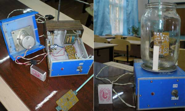
Encyclopedia of radio electronics and electrical engineering / Ham Radio Technologies The vast majority of radio amateurs use printed circuit boards to mount their designs, which make it possible to mount the circuit of interest better and faster. If in the process of designing, marking, wiring and drawing a pattern on a printed circuit board, computer technology is now increasingly used. In extreme cases, drawing on the board is greatly facilitated by using a permanent felt-tip pen, instead of a drawing pen and acid-resistant paint. The board etching process remains the same, the same photocell, etching solution and constant mixing of the solution to speed up board etching. The whole pickling process takes a lot of time plus constant absences to mix the solution. Of course, the pickling time can be shortened by using more aggressive reagents, such as nitric acid, but this produces a large amount of harmful gases that require outdoor work or the use of a special fume hood. Constant heating of the solution is also not practical. There is another way to speed up etching, this is the constant mixing of the solution (shaking the photocell) and it is used by radio amateurs. To get rid of these inconveniences, I developed a machine to speed up the process of etching printed circuit boards. The principle of its operation is based on the constant mixing of the solution, as a result of which it acts more actively on the copper coating of the board and contributes to the constant removal of reaction products. Initially, there was an attempt to use the device according to the "mixer" principle, that is, a fixed solution and a rotating board, but such a device turned out to be cumbersome, the motor with the gearbox was located on top of the pickling tank, the system was unstable. To inspect the board, I had to lift the entire device, hold it above the container, no matter what the solution got on the desktop. Having abandoned this option, another one was chosen, in my opinion, more optimal in all respects, let's call it the "concrete mixer" principle. In this device, the board intended for etching is fixed motionless, and the vessel with the solution rotates. Since radio amateurs tend to miniaturize their devices, and, accordingly, circuit boards. The vast majority of printed circuit boards made in a home workshop are small in size. The optimal container for the solution from all sides, in my opinion, turned out to be a standard glass jar with a capacity of one liter, it allows you to process boards with a size of 100 * 70 mm. The device turned out to be compact, stable, when folded it takes up little space on the desktop. The apparatus uses a device for periodically switching on an electric motor, designed for a more efficient etching process. With each start of the electric motor, the board is washed more intensively with the solution, washing away the products of the etching process. The "Work" and "Pause" times are chosen arbitrarily, in my case the engine is running for 5 minutes, and the engine is off for 2 minutes. The general view of the device is shown in the figures below, the base is a plastic case, in which an electric motor with a gearbox (11), a step-down transformer (4) and a board for periodic switching on of the electric motor (3) are mounted.
Fig. 1 Figure 2 shows the drawings of the parts. A rotary table (5) made of aluminum alloy on a lathe is mounted on the output shaft of the gearbox. A through hole with a diameter corresponding to the diameter of the gearbox output shaft is drilled in the center of the rotating table. A hole with a diameter of 2,4 mm is also drilled on the neck of the rotating table, in which an M3 thread is cut, into which a locking screw is screwed, which serves as a lock on the gearbox shaft. On the horizontal plane of the table at an angle of 600, six holes are drilled for the M3 thread, three of which are used to fasten the limiting posts (8) located at an angle of 1200. Racks are made of sheet aluminum 1,5-2 mm thick. The plastic pad (7) protects the turntable from accidental ingress of mortar and is secured to the turntable with three M3 countersunk screws. As an overlay, you can use sheet rubber, cut out according to the diameter of the table and laid between the limiting posts. The vertical rod consists of 3-4 knees of the telescopic antenna and is fixed on the rear wall of the device with M3 screws.
Fig. 2 This solution allows you to very simply adjust the height of the board immersion in the solution, as well as in the non-working position, adjust to the minimum size. A sleeve (9) made of any material (aluminum, plastic) is fixed at the upper end of the telescopic rod by any available means. In this case, the sleeve is taken from the children's constructor. A hole is drilled in the side wall of the sleeve and an M3 thread is cut into it, into which a horizontal rod (10) is screwed, having an M3 thread at both ends. The length of the rod is selected depending on the distance of the telescopic rod from the center of the rotary table. At the other end of the horizontal rod, a sleeve (13) is attached, which has a through hole with a diameter of 4-5 mm, depending on the diameter of the plastic rod (12), which can be used as a large knitting needle. A through hole is also drilled in the side wall of the bushing (3) and an M3 thread is cut. On the one hand, the thread serves for fastening to a horizontal bar (2), and on the other hand, a lamb for fixing a plastic rod is screwed in, which allows you to quickly raise the board for inspection. The printed circuit board is fastened to the bar using two rubber rings (6) made of a hose of a suitable diameter, which move along the bar with friction and thereby fix the board. After pickling is completed, the fixing lamb is released and the rod with the fixed board rises up, the remaining solution flows back into the pickling tank. The board is washed by replacing the container with the solution with clean water, immersing the board in it and putting it into operation. This mode more thoroughly flushes out the remaining solution, especially from the holes. As mentioned above, the entire device is mounted in a plastic case. An electric motor with a gearbox (11) is fixed on the upper removable cover. In my case, an electric motor with a built-in gearbox of the MKM-6V type is used from the automatic alarm and distress transmitter of the Plot emergency radio station. The frequency of rotation of the output shaft of the gearbox at a supply voltage of 9 volts is about 40-60 rpm. In principle, any electric motor with a gearbox can be used. A power transformer (4) is also installed in the housing with a voltage on the secondary winding of 10-12 Volts and a load current of up to 0,5 A, which provides power to the electric motor through the contacts of the K1 relay and the non-periodic switching board. In principle, periodic switching can be omitted by supplying the engine directly from the rectifier. The front panel of the device has an LED indicator and a power switch. The periodic switching machine is assembled according to the scheme of Fig. 3, the capacitors C1 and C3, the diodes VD1 and VD2 and the elements of the microcircuit D1.1 - D1.3 form a pulse shaper that controls the transistor VT1.4 through the inverter D1, in the collector circuit of which the relay K1 is switched on, the contacts of which control the operation of the electric motor.
Fig. 3 The scheme of the machine is assembled on a printed circuit board made of foil getinax (Fig. 4) 1,5-2 mm thick, 98 mm x 35 mm in size. It is permissible to replace the K561LA7 microcircuit with K176LA7, the diodes VD1, VD2, VD3 are replaced with KD102A, B. RES6 passport RS 4524.303 is used as a relay. Electrolytic capacitors are imported, it is better to take the highest possible operating voltage, they have less leakage current. A properly assembled machine starts working immediately, you just need to select the values of the resistors R1 and R6 for the required intervals of operation and pause. Work with the device as follows. A printed circuit board prepared for etching is fixed to a plastic rod (12) using rubber rings (6). Then a telescopic rod is extended and a bar with a board is inserted into the sleeve (13) and fixed with a lamb. The etching solution is poured into the etching container (standard liter glass jar) and placed on the turntable (5). After loosening the fixing lamb, release the board into the solution and fix it again with the locking lamb. Turning on the power of the device. Periodically, the board can be lifted to inspect and determine the end of the etching process. Using the device allows you to speed up the entire process by 3-4 times even in a solution with room temperature and frees you from constant mixing of the solution.
Fig. 4 Board drawing in .lay format (10Kb) Author: I.V. Ankudinov - aiv55 [dog] mail.ru; Publication: cxem.net
Artificial leather for touch emulation
15.04.2024 Petgugu Global cat litter
15.04.2024 The attractiveness of caring men
14.04.2024
▪ Soluble electronics suitable for implantation created ▪ Pocket Nuclear Resonance Scanner ▪ Titanic is being eaten by bacteria ▪ Rugged smartphone Blackview BV8900 with a thermal imager
▪ website section Television. Article selection ▪ article In the main - unity, in the secondary - freedom, in everything - love. Popular expression ▪ article Are there man-eating tigers? Detailed answer ▪ article Sesame. Legends, cultivation, methods of application ▪ article What is cool, what is raw? Physical experiment. physical experiment
Home page | Library | Articles | Website map | Site Reviews
www.diagram.com.ua |


 Leave your comment on this article: