|
|


 Arabic
 Bengali
 Chinese
 English
 French
 German
 Hebrew
 Hindi
Hindi Italian
 Japanese
 Korean
 Malay
Malay Polish
 Portuguese
 Spanish
 Turkish
 Ukrainian
 Vietnamese
|
ENCYCLOPEDIA OF RADIO ELECTRONICS AND ELECTRICAL ENGINEERING Radiators and cooling. Encyclopedia of radio electronics and electrical engineering
Encyclopedia of radio electronics and electrical engineering / Ham Radio Technologies There is a well-known law in physics, electrical engineering and atomic thermodynamics - the current flowing through the wires heats them up. Joule and Lenz came up with it, and they turned out to be right - the way it is. Everything that runs on electricity, one way or another, part of the passing energy transfers into heat. It just so happens in electronics that the most heat-affected object in our environment is air. It is to the air that the heating parts transfer heat, and from the air it is required to receive heat and put it somewhere. Lose, for example, or scatter on your own. We call the process of heat transfer cooling. Our electronic designs also dissipate a lot of heat, some more than others. Voltage stabilizers are heated, amplifiers are heated, the transistor that controls the relay or even just a small LED is heated, except that it heats up quite a bit. Okay, if it gets a little warm. Well, if it is fried so that you can’t hold your hand? Let's take pity on him and try to help him somehow. So to speak, to alleviate his suffering. Recall the device of the heating battery. Yes, yes, the same ordinary battery that heats the room in winter and on which we dry socks and T-shirts. The larger the battery, the more heat will be in the room, right? Hot water flows through the battery, it heats the battery. The battery has an important thing - the number of sections. Sections are in contact with air, transferring heat to it. So, the more sections, that is, the larger the area occupied by the battery, the more heat it can give us. By welding a couple more sections, we can make our room warmer. True, at the same time, the hot water in the battery can cool down, and there will be nothing left for the neighbors. Consider the transistor device.
On a copper base (flange) 1on a substrate 2fixed crystal 3. It connects to outputs 4. The whole structure is filled with plastic compound 5. The flange has a hole 6for installation on a radiator.
How to make a crystal colder? We cannot change the device of the transistor, this is understandable. The creators of the transistor also thought about this, and for us, the martyrs, they left the only path to the crystal - the flange. A flange is like a single section of a battery - frying is frying, but heat is not transferred to the air - a small contact area. This is where the scope for our actions is given! We can build up the flange, solder a couple more sections to it, that is, a large copper plate, since the flange itself is copper, or fix the flange on a metal blank called a radiator. Fortunately, the hole in the flange is prepared for a bolt with a nut. What is a radiator? I’ve been repeating for the third paragraph about him, but I haven’t really said anything! Okay, let's see:
As you can see, the design of radiators can be different, these are plates, and fins, and there are also needle-shaped radiators and various others, just go to the radio parts store and go over the shelf with radiators. Radiators are most often made of aluminum and its alloys (silumin and others). Copper radiators are better, but more expensive. Steel and iron radiators are used only at very low power, 1-5W, as they slowly dissipate heat. The heat released in a crystal is determined by a very simple formula P = U * I, where P is the power dissipated in the crystal, W, U = voltage on the crystal, V, I is the current through the crystal, A. This heat passes through the substrate to the flange, where it is transferred to the radiator. Further, the heated radiator comes into contact with air and heat is transferred to it, as the next participant in our cooling system. Let's look at the complete transistor cooling circuit.
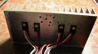
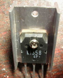
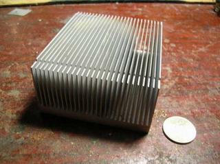
We have two pieces - this is a radiator 8and a gasket between the heatsink and the transistor 7. It may not be, which is both bad and good at the same time. Let's figure it out. I'll tell you about two important parameters - these are thermal resistances between the crystal (or junction, as it is also called) and the transistor case - Rpc and between the transistor case and the radiator - Rcr. The first parameter indicates how well heat is transferred from the crystal to the flange of the transistor. For example, Rpc, equal to 1,5 degrees Celsius per watt, explains that with an increase in power by 1 W, the temperature difference between the flange and the radiator will be 1,5 degrees. In other words, the flange will always be colder than the crystal, and this parameter shows how much. The smaller it is, the better the heat is transferred to the flange. If we dissipate 10W of power, then the flange will be colder than the crystal by 1,5 * 10 = 15 degrees, and if 100W, then by all 150! And since the maximum temperature of the crystal is limited (it cannot be fried to a white heat!), The flange must be cooled. At the same 150 degrees. For example: The transistor dissipates 25W of power. Its Rpc is 1,3 degrees per watt. The maximum temperature of the crystal is 140 degrees. This means that there will be a difference of 1,3 * 25 = 32,5 degrees between the flange and the crystal. And since the crystal cannot be heated above 140 degrees, we are required to maintain the flange temperature not hotter than 140-32,5=107,5 degrees. Like this. And the Rcr parameter shows the same, only the losses are obtained on the same notorious gasket 7. Its Rcr value can be much larger than Rpc, therefore, if we are designing a powerful unit, it is undesirable to put transistors on gaskets. But still, sometimes you have to. The only reason to use a spacer is if you need to isolate the heat sink from the transistor, because the flange is electrically connected to the middle terminal of the transistor package. Let's look at another example here. The transistor is fried at 100W. As usual, the temperature of the crystal is no more than 150 degrees. Rpk it has 1 degree per watt, and even on the gasket, which has Rkr 2 degrees per watt. The temperature difference between the crystal and the radiator will be 100*(1+2)=300 degrees. The radiator must be kept not hotter than 150-300 = minus 150 degrees: Yes, my dears, this is the very case that only liquid nitrogen will save: horror! It is much easier to live on a radiator for transistors and microcircuits without gaskets. If there are none, and the flanges are clean and smooth, and the radiator sparkles with brilliance, and even heat-conducting paste is put, then the Rcr parameter is so small that it is simply not taken into account. Got it? Let's go further! There are two types of cooling - convection and forced. Convection, if we remember school physics, is the independent distribution of heat. The same goes for convection cooling - we installed a radiator, and he himself will somehow sort out the air there. Convection-type radiators are most often installed outside the devices, like in amplifiers, have you seen? On the sides are two metal plate gizmos. From the inside, transistors are screwed to them. Such radiators cannot be covered, air access is closed, otherwise the radiator will have nowhere to put the heat, it will overheat itself and refuse to receive heat from the transistor, which will not think for a long time, it will also overheat and: you yourself understand what will happen. Forced cooling is when we force the air to blow more actively around the radiator, making its way along its ribs, needles and holes. Here we use fans, various air cooling channels and other methods. Yes, by the way, instead of air, it can easily be water, and oil, and even liquid nitrogen. Powerful generator tubes are often cooled by running water. How to recognize a radiator - is it for convection or forced cooling? Its efficiency depends on this, that is, how quickly it can cool the hot crystal, what flow of thermal power it can pass through itself. We look at the photos.
The first radiator is for convection cooling. Large fin spacing ensures free airflow and good heat dissipation. A fan is put on top of the second radiator and blows air through the fins. This is forced cooling. Of course, you can use both those and those radiators everywhere, but the whole question is their efficiency. Radiators have 2 parameters - this is its area (in square centimeters) and the coefficient of thermal resistance of the radiator-environment Rrs (in Watts per degree Celsius). The area is calculated as the sum of the areas of all its elements: the area of the base on both sides + the area of the plates on both sides. The area of \uXNUMXb\uXNUMXbthe ends of the base is not taken into account, so there will be very few square centimeters. Example: the radiator from the example above for convection cooling.
The coefficient of thermal resistance radiator-environment Rpc shows how much the temperature of the air leaving the radiator will increase with an increase in power by 1W. For example, a Rpc of 0,5 degrees Celsius per watt tells us that the temperature will increase by half a degree for 1W of heat. This parameter is considered to be three-story formulas and our feline minds are by no means within the power: Rpc, like any thermal resistance in our system, the smaller the better. And you can reduce it in different ways - for this, radiators are blackened chemically (for example, aluminum darkens well in ferric chloride - do not experiment at home, chlorine is released!), There is also the effect of orienting the radiator in the air for better passage along the plates (a vertical radiator cools better than a recumbent one). It is not recommended to paint the radiator with paint: paint is an excess thermal resistance. If only slightly, so that it was dark, but not a thick layer! The application contains a small program, in which you can calculate the approximate area of \uXNUMXb\uXNUMXbthe radiator for some microcircuit or transistor. With it, let's calculate the radiator for some power supply. Power supply circuit.
The power supply outputs 12 volts at a current of 1A. The same current flows through the transistor. At the input of the transistor is 18V, at the output is 12V, which means that a voltage of 18-12 \u6d 6V drops on it. Power dissipated from the transistor crystal is 1V * 6A \u2d 2335W. The maximum temperature of the crystal for 150SC120 is 1,5 degrees. Let's not use it in extreme conditions, let's choose a lower temperature, for example, XNUMX degrees. The thermal resistance of the junction-case Rpc for this transistor is XNUMX degrees Celsius per watt. Since the transistor flange is connected to the collector, let's provide electrical insulation to the heatsink. To do this, we put an insulating gasket made of heat-conducting rubber between the transistor and the radiator. The thermal resistance of the gasket is 2 degrees Celsius per watt. For good thermal contact, let's drop a little PMS-200 silicone oil. This is a thick oil with a maximum temperature of +180 degrees, it will fill the air gaps that are necessarily formed due to the unevenness of the flange and radiator and improve heat transfer. Many use KPT-8 paste, but many consider it not the best heat conductor. We will bring the radiator to the back wall of the power supply, where it will be cooled by room air + 25 degrees. We will substitute all these values into the program and calculate the area of the radiator. The resulting area of 113 sq. cm is the area of the radiator, designed for long-term operation of the power supply in full power mode - more than 10 hours. If we do not need so much time to drive the power supply, we can get by with a smaller, but more massive radiator. And if we install a radiator inside the power supply, then there is no need for an insulating gasket, without it the radiator can be reduced to 100 sq.cm. In general, my dears, the stock does not pull the pocket, do you all agree? Let's think about the margin, so that it is both in the area of \uXNUMXb\uXNUMXbthe radiator and in the limiting temperatures of transistors. After all, not just anyone, but you yourself will have to repair devices and change overcooked transistors! Remember this! Good luck. Publication: radiokot.ru
Artificial leather for touch emulation
15.04.2024 Petgugu Global cat litter
15.04.2024 The attractiveness of caring men
14.04.2024
▪ Cookies baked in space for the first time ▪ Permanent Internet in the car ▪ Meike 85mm F/1.8 full-frame autofocus lens
▪ site section Infrared technology. Article selection ▪ article by François VI de La Rochefoucauld. Famous aphorisms ▪ article Operation of observation fire towers. Standard instruction on labor protection ▪ article Three layers of liquid. Focus Secret
Home page | Library | Articles | Website map | Site Reviews
www.diagram.com.ua |


 Leave your comment on this article: