|
|


 Arabic
 Bengali
 Chinese
 English
 French
 German
 Hebrew
 Hindi
Hindi Italian
 Japanese
 Korean
 Malay
Malay Polish
 Portuguese
 Spanish
 Turkish
 Ukrainian
 Vietnamese
|
ENCYCLOPEDIA OF RADIO ELECTRONICS AND ELECTRICAL ENGINEERING Two photocells. Encyclopedia of radio electronics and electrical engineering
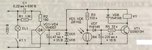
Encyclopedia of radio electronics and electrical engineering / Lighting The scheme of the device installed in the entrance of a residential building and turning on the lighting in it at nightfall, and turning it off at dawn, is shown in Fig. one.
When the photoresistor R4 is illuminated, its resistance decreases, the voltage drop across it decreases, the transistor VT1 closes, the relay K1 and the EL1 lamp turn off, when the photoresistor is shaded, everything happens in the reverse order and the lamp turns on. Capacitor C1 - K73-17. It can be replaced with a foreign-made film capacitor for a voltage of at least 630 V DC or 275 V AC. Instead of a foreign SS9013H transistor, a domestic KT680A is suitable. The photoresistor is imported, the type could not be determined. But its resistance, equal to 30 kOhm in the dark, in daylight decreases to 6 kOhm. The relay used was imported SRD-24VDC-SL-A from SONGLE. Its winding has a resistance of 1600 ohms. The actuation current measured by the M-830V multimeter is 8,76 mA, the release current is 2,58 mA. The relay contacts are designed for switching loads up to 1200 VA (at a voltage of 250 V AC). A more complex version of the photorelay is offered by V. KONOVALOV from Irkutsk. He developed it to control the emergency lighting of the territory adjacent to the cottage or dacha, allowing only to navigate it at night. The total power of luminaires of such lighting is usually small and does not exceed a tenth of the power of the main lighting.
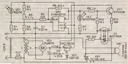
The diagram of a photorelay that allows you to control lamps with a total power of up to 600 W at a voltage of 220 V is shown in fig. 2. The power consumption of this appliance is less than 5W. The VD1 photodiode is installed where it will not be exposed to light from the headlights of vehicles and from the windows of the house. Its illumination should depend only on the intensity of natural and main artificial lighting of the territory. The length of the wires going to the photodiode should be kept to a minimum. In order to avoid interference, they cannot be laid in the same bundle with the wires of the mains or near these wires. The DA1 op-amp works as a comparator that compares the voltage dependent on the illumination of the photodiode coming from the divider formed by this photodiode and resistor R1 with the exemplary voltage coming from the engine of the tuning resistor R3 . Resistor R6 creates a positive feedback that not only accelerates the operation of the comparator, but also provides a hysteresis of its switching characteristics. As a result, the photorelay turns off the standby lighting when the photodiode is illuminated more than it turns on. This eliminates the chaotic repeated switching on and off of the lamps when the illumination is close to the threshold. Capacitor C1 is connected to the inverting input of the op-amp to suppress interference. The operation of the photo relay - the setting of a high voltage level at the output of the op-amp - is signaled by the inclusion of the HL1 LED. At the same time, a current begins to flow through the radiating diode of the optocoupler U1 included in the emitter circuit of the transistor VT1. The phototriac of the optocoupler opens and opens a powerful triac VS1, which closes the power circuit of the emergency lighting lamps connected to the XS1 socket.
The supply voltage to the op-amp DA1 is supplied through the integral stabilizer DA2. Its stabilization voltage is increased by approximately 0,7 V relative to the nominal 9 V by connecting the VD3 diode in the forward direction to the common wire of the stabilizer microcircuit. Transformer T1 - any step-down power of at least 5 VA with a secondary winding voltage of about 12 V, for example TS20-7 3. She and the transformer T1 are fixed in the case of one of the emergency lighting fixtures, and the VD1 photodiode is fixed on the outside of the case, taking into account the above recommendations.
It is necessary to select a replacement for the triac TS 106-6 among similar devices with a permissible voltage of at least 600 V and withstanding the total current of all emergency lighting lamps. The triac must be equipped with a heat sink measuring 20x40x50 mm. The trimmer resistor R3 achieves a low voltage level at the output of the op-amp DA1 when the photodiode VD1 is illuminated with a 20 ... 40 W lamp from a distance of 2 ... 3 m. When the light is blocked by the hand, the photo relay should work, which is fixed by the glow of the HL1 LED. Author: S. Kosinsky, pos. Orsha, Tver region; Publication: radioradar.net
Machine for thinning flowers in gardens
02.05.2024 Advanced Infrared Microscope
02.05.2024 Air trap for insects
01.05.2024
▪ Analogix SlimPort ANX7688 Transmitter ▪ Budget DC-DC converters Mean Well SPA02 and SPB03 ▪ The most powerful private solar power plant launched
▪ section of the site Audio Art. Article selection ▪ article by Anthony Ashley Cooper Shaftesbury. Famous aphorisms ▪ article What is rheumatism? Detailed answer ▪ Dracaena article. Legends, cultivation, methods of application ▪ article Electric incandescent lamps. Encyclopedia of radio electronics and electrical engineering
Home page | Library | Articles | Website map | Site Reviews
www.diagram.com.ua |


 Leave your comment on this article: