|
|


 Arabic
 Bengali
 Chinese
 English
 French
 German
 Hebrew
 Hindi
Hindi Italian
 Japanese
 Korean
 Malay
Malay Polish
 Portuguese
 Spanish
 Turkish
 Ukrainian
 Vietnamese
|
ENCYCLOPEDIA OF RADIO ELECTRONICS AND ELECTRICAL ENGINEERING The counter of people in the room that controls the lighting. Encyclopedia of radio electronics and electrical engineering
Encyclopedia of radio electronics and electrical engineering / Lighting When people come in and out of a room during the day, the light that the last person who left forgot to turn off often stays on all night. The proposed device, constantly counting incoming and outgoing, always "knows" how many people are inside. The device automatically turns on the lighting as soon as someone enters the room, and turns it off when everyone has left. The device was built on the PIC12F629 microcontroller, which processes the signals of two Opto-Bero 3RG7010-0CC00 optical contactless object position sensors from Siemens, installed on the door jamb so that each incoming one crosses the sensitive zone first of the first and then the second sensor, and the outgoing one crosses them in the reverse order .
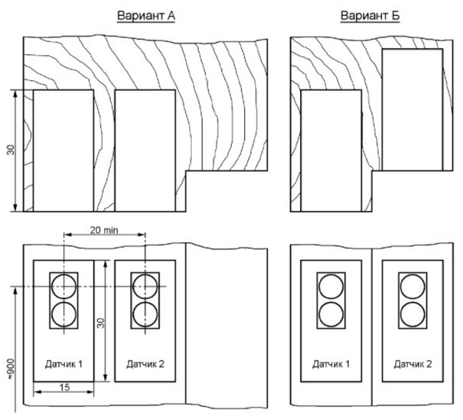
Possible options for installing sensors are shown in fig. 1. Option A is used if the jamb is wide enough and it is possible to place two sensors in the recesses cut in it, placing their sensitive surfaces in the same plane. Otherwise, option B is used. One should not be afraid of shading one of the sensors with a closed door, this situation is taken into account in the microcontroller program and does not lead to errors. The sensors should be installed at a height of about 900 mm. If they are lower, there may be an unwanted reaction on both legs of a person crossing the sensitive zones of the sensors in turn, resulting in a counting error. When using the device in a room with several doors, the sensors must be installed in the openings of each of them. They are connected in parallel with the sensors of the first pair. Instead of relatively expensive branded optical sensors, you can use self-made ones, for example, built according to the description in the article by Yu. Vinogradov "Laser pointer in the security alarm" ("Radio", 2002, No. 7, pp. 43, 44). In this case, the radiation source of each such sensor must be installed exactly opposite its receiver, which must be placed on the opposite side of the doorway.
The counter circuit is shown in fig. 2. To block XT1, in accordance with the numbers of contacts, connect the conclusions sensor, which, when a person enters the room, is triggered first, and to block XT2 - the conclusions of the one that triggers second. A supply voltage of 1 V is supplied to the sensors through contacts 3 and 12 of the blocks. When there is no reflective object in the sensitive zone of the sensor, the pnp transistor located in this sensor is open, the emitter of which is connected to terminal 1, and the collector to terminal 2. If such an object is present, the sensor fires and its internal transistor closes. So far, no sensor has worked, transistors VT1 and VT2 are open, so the logical voltage levels at the inputs GP1 and GP2 of the DD1 microcontroller are low. When a sensor is triggered, the transistor VT2 or VT1 connected to its output 2 closes. The level at the GP1 input (if the first sensor is triggered) or at the GP2 input (if the second sensor is triggered) becomes high. The XT4 block is connected in series to the break in the lighting lamp circuit instead of a conventional switch or in parallel with it. The SA1 switch connected to the XT3 block can break the winding circuit of the K1 executive relay, turning off the automatic lighting control. If this switch is not needed, the contacts of the XT3 block should be closed with a jumper. At the beginning of its work (when power is applied), the microcontroller program resets the counter of sensor activations organized in it, and sets low levels at the outputs GP0 and GP4. LED HL1 in this state is off, the transistor VT3 is closed. The current through the coil of the relay K1 does not flow, so the lighting is turned off by its open contacts. When a person passes by the sensors, the program determines the order of their operation. If sensor No. 1 was triggered first, followed by sensor No. 2, it means that a person has entered the room. The counter value increases by 1. The reverse order of their operation shows that the person has left, and the counter value decreases by 1. Thus, the number accumulated in the counter is always equal to the number of people in the room. If it is greater than zero (the maximum possible value is 255), GP0 output is high and the lighting is on. If it is equal to zero (it cannot become less, this is provided for in the program), then there are no people in the room and the lighting is turned off. Accounting for each incoming is confirmed by a series of flashes of the HL1 LED. Their number in the series is equal to the number of people currently in the room. A person who stops in a doorway does not change the value in the counter. It will change only if it continues to move in the same direction. The device is powered by any 12 V DC voltage source, consuming a current of no more than 20 mA in standby mode, to which, when the lighting is turned on, the current flowing through the relay winding K1 is added. A 1 V voltage regulator is made on the DA5 chip to power the microcontroller.
The printed circuit board of the device is shown in fig. 3. Microcontroller PIC12F629-I/P can be replaced by PIC12F675-I/P. Instead of an integrated stabilizer 78L05, you can install another one at +5 V, including a more powerful one - 7805 (KR142EN5A), taking into account the difference in the purpose of its conclusions. Transistors 2N2222 are replaced, for example, with KT315A, and a replacement for the transistor 2N2926 should be selected taking into account the operating current of the relay winding K1. Relay contacts must be capable of withstanding 220 V AC and current (including starting) of the lamps they control. Suitable, for example, relay TRIL-1 2VDC-FB-2CM. The meter microcontroller program can be downloaded from ftp://ftp.radio.ru/pub/2013/11/account.zip. Author: V. Yushin
Machine for thinning flowers in gardens
02.05.2024 Advanced Infrared Microscope
02.05.2024 Air trap for insects
01.05.2024
▪ Websites learn how visitors feel ▪ Innovative orbital housing concept from Airbus ▪ The moon may have been responsible for the sinking of the Titanic
▪ section of the Garland website. Article selection ▪ article A teaspoon per hour. Popular expression ▪ What were the main features of the Hellenistic era? Detailed answer ▪ article Mullein officinalis. Legends, cultivation, methods of application ▪ article Invulnerable napkin. Focus Secret
Home page | Library | Articles | Website map | Site Reviews
www.diagram.com.ua |


 Leave your comment on this article: