|
|


 Arabic
 Bengali
 Chinese
 English
 French
 German
 Hebrew
 Hindi
Hindi Italian
 Japanese
 Korean
 Malay
Malay Polish
 Portuguese
 Spanish
 Turkish
 Ukrainian
 Vietnamese
|
ENCYCLOPEDIA OF RADIO ELECTRONICS AND ELECTRICAL ENGINEERING ECG on discrete elements for T8 lamps. Encyclopedia of radio electronics and electrical engineering
Encyclopedia of radio electronics and electrical engineering / Lighting The article proposes a simple electronic ballast for T8 fluorescent lamps, assembled on discrete elements. Fluorescent lamps have been the most popular light source after incandescent lamps for many decades. As you know, their operation requires a ballast (ballast) - a device that provides stable ignition and maintains the required operating current in the lamp. Many books and publications are devoted to electronic ballasts (electronic ballasts), for example [1, 2]. The universal electronic ballast described in [1] provides a "warm" start for lamps and a very low ripple coefficient of the luminous flux (about 1%). But such devices are quite difficult to repeat in amateur radio conditions, require rare components and are "sensitive" to the PCB trace, especially to the wiring of the common wire. In the proposed article, a simpler version of the electronic ballast, assembled from common radio components, is considered. The electronic ballast circuit is shown in fig. 1. It is designed to work with four 8W T18 lamps or two 36W lamps (Fig. 2).
Main Specifications
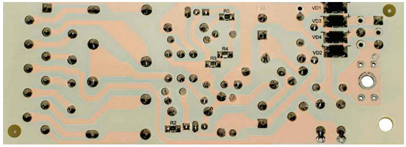
The half-bridge self-oscillator of the "electronic transformer" for halogen lamps, described in [3], was taken as a basis. The differences are in the output stage, in the presence of a passive power corrector (in the "electronic transformer" for halogen lamps [3] it is not needed) and a modified start circuit. Otherwise, the principle of its operation is similar. The output stage is two series LC circuits connected in parallel: T2 (winding I), C11 and T3 (winding I), C12. Each circuit is designed for a load of 36 W, i.e. two 18 W lamps or one 36 W lamp. The resonant frequency of the circuits is about 60 kHz. The passive power corrector is assembled on diodes VD5-VD8 and capacitors C5, C6. It serves to adjust the shape of the current consumed by the device. This provides a power consumption factor close to unity. If desired, the corrector can be excluded, but in this case the power factor will not exceed 0,5 ... 0,6. The oscillator is launched without a dinistor "usual" in such devices. This made it possible to simplify the device and avoid the main drawback of the dinistor start, which, according to the author, is related to the spread of the parameters of the dinistor itself, which can lead to an unstable start of the oscillator at low mains voltage. The launch is carried out by applying a bias voltage "directly" to the base of the transistor VT2 through resistors R3, R4, as well as to the oscillatory circuit formed by elements C9, L2, winding II of the transformer T1. The fluctuations that arise in it in total with the applied bias voltage lead to the opening of the transistor VT2. The resistance of the resistors R3, R4 is chosen so that the current flowing through them is insufficient to keep VT2 open at the moment the reverse polarity voltage appears in the winding II of the transformer T1, i.e., at the moment when the transistor VT1 opens. Changing the start circuit and increasing the operating frequency of the converter from 35 kHz (in the "electronic transformer" for halogen lamps) to 65 kHz made it possible to achieve a stable start of the ballast when the mains voltage drops to 145 ... 155 V, as well as to slightly reduce the dimensions of the output transformers T2 and T3. The ballast is assembled on a printed circuit board measuring 116x42 mm from fiberglass laminated on one side. The drawing of the conductors is shown in fig. 3, the location of the elements - in fig. 4. All elements for surface mounting (VD1-VD4, R2-R5) are located on the side of printed conductors, output elements are on the opposite side of the board. Capacitors C2-C4, C7, C10, C13 - any film, suitable dimensions for a rated voltage of at least 400 V (direct current - VDC), C11, C12 - for 1600 V (VDC), C1 - ceramic for a voltage of 1500 V (VDC ), but it is better to use a Y-class noise suppression capacitor with a rated voltage of at least 275 V (alternating current - VAC). Diodes FR107 (VD5-VD12) can be replaced by any high-speed rectifier with a reverse voltage of at least 600 V and a direct current of at least 300 mA. Transformer T1 is wound on a ring magnetic circuit (magnetic permeability - 2300) with an outer diameter of 9, an inner diameter of 5 and a ring height of 3,5 mm. Windings I and II contain four turns each, winding III has two turns of a single-core wire with a diameter of 0,3 mm. The direction of all windings must be the same. Windings I and II must have an inductance of 16 ± 15% µH, winding III - 4 µH. The output transformers T2 and T3 are wound on E20/10/6 magnetic cores made of N27 (Epcos) material or similar with a non-magnetic gap of about 1 mm. The primary windings contain 130 turns of a bundle of six wires with a diameter of 0,1 ... 0,15 mm. In the absence of a six-core bundle, a single-core wire with a diameter of 0,25 ... 0,35 mm can be used, however, in this case, the heating of transformers will increase by 10 ... 15 оC. The secondary windings have 13 turns of a single-core wire with a diameter of 0,3 mm. The inductance of the primary windings should be 1±15% mH. Chokes L1, L2 - standard, for example EC24.
Photos of the printed circuit board of the assembled device are shown in fig. 5, fig. 6. Photos of the working ballast with lamps - in fig. 7 and fig. 8. A correctly assembled device starts working immediately and does not require adjustment.
Literature
Author: V. Lazarev
Machine for thinning flowers in gardens
02.05.2024 Advanced Infrared Microscope
02.05.2024 Air trap for insects
01.05.2024
▪ Alloy with giant barymagnetic effect ▪ World's smallest Full HD display
▪ section of the site Grounding and grounding. Selection of articles ▪ article Live chronology. Popular expression ▪ article Part of what toy was used in the first electrocardiograph? Detailed answer ▪ article Joiner-carpenter. Job description ▪ article Flexible stick. Focus secret
Home page | Library | Articles | Website map | Site Reviews
www.diagram.com.ua |


 Leave your comment on this article: