|
|


 Arabic
 Bengali
 Chinese
 English
 French
 German
 Hebrew
 Hindi
Hindi Italian
 Japanese
 Korean
 Malay
Malay Polish
 Portuguese
 Spanish
 Turkish
 Ukrainian
 Vietnamese
|
ENCYCLOPEDIA OF RADIO ELECTRONICS AND ELECTRICAL ENGINEERING Programmable garland switch. Encyclopedia of radio electronics and electrical engineering
Encyclopedia of radio electronics and electrical engineering / Color and music settings Only four microcircuits, the same number of transistors and trinistors, and a dozen resistors and a capacitor will be needed to build an automaton (Fig. 1), which provides ten options for turning on four New Year's lamp garlands. The desired work program is set with switches SA 1 and SB 1.
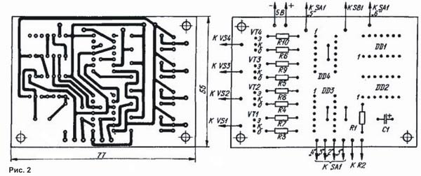
A master oscillator is assembled on the elements DD 2.1 - DD 2.3, the pulse repetition rate of which depends on the capacitance of the capacitor C1 and the total resistance of the resistors R1 and R2. Variable resistor R2 "Frequency" smoothly change the pulse repetition rate, and hence the switching frequency of the garlands. From the generator output (pin 8 of the DD 2 chip), the pulses are fed to the clock inputs of the triggers DD 3.1 - DD 4.2, on which the shift register is made. Depending on the position of the movable contact of the SA1 switch, there will be one or another sequence of appearance of the levels of logical signals (0 or 1) on the direct and inverse trigger outputs. Pushbutton switch SB1 "Adjustment" is used to start the shift register and adjust the specified program for switching garlands. Depending on the duration of holding the switch button in the pressed state (when its movable contact is connected to the lower one according to the fixed circuit), with the same position of the SA1 switch, several types of combinations of switching on garlands can be obtained. Each garland is connected in series with a trinistor, the control electrode of which is supplied through a limiting resistor with a constant voltage of 5 V, and a transistor switch is connected in parallel to the control electrode and the cathode. When the logic level is 0 at the base of the transistor (it comes from the inverse trigger output), the transistor is closed, but the trinistor is open. Garland included. As soon as the logic level 1 enters the base, the transistor opens and shunts the control electrode of the trinistor. The trinistor closes, the garland goes out. As already mentioned, by varying the duration of pressing the SB1 button, you can "program" a wide variety of combinations of switching on garlands. So, in position "1" of switch SA 1, it is possible to obtain such combinations (dash combined simultaneously burning garlands, semicolons - combination options): 1, 2, 3, 4; 1-2, 2-3, 3-4, 4-1; 1-2-3, 2-3-4, 3-4-1, 4-1-2; 1-3, 2-4. In position "2" the combinations are: 1, 1-2, 1-2-3, 1-2-3-4, 2-3-4, 3-4, 4; 2-3, 1-3-4, 2-4, 3, 1-4, 2, 1-3, 1-2-4; in position "3": 2-3, 1-3-4, 1-2-4; 1-4, 2, 3; in position "4": 1, 1-2, 1-2-3, 2-3-4, 3-4, 4; in position "5": 1-3, 2-4. In position "6" comes into operation node, executed on the elements DD1.1 - DD1.3, DD2.4 and performing the operation "EXCLUSIVE OR". The garlands begin to turn on in a changing sequence, giving the impression of repeating the variety of previous programs. In position "7" the operation of the switch stops, and all the garlands flash. The garlands are powered from the mains through a full-wave rectifier on VD1-VD4 diodes, and microcircuits and transistor switches are powered from any source with a stabilized output voltage of 5 V at a load current of up to 200 mA. With the trinistors and diodes indicated in the diagram, the power of each garland can be up to 500 watts. Transistors - any of the KT315 series; trinistors - KU201, KU202 with indices K-N; diodes - any, designed for a reverse voltage of at least 300 V and a rectified current exceeding the total current consumption of the garlands. Fixed resistors - MLT-0.125, variable - SP-1; capacitor - K50-6; switch SA 1 - biscuit, for example 11P1N (the number of its positions is limited by permutation of the latch), SB 1 - button MT 1-1. Some parts of the machine are mounted on a printed circuit board (Fig. 2) made of one-sided foil fiberglass, which is installed on a common chassis made of insulating material. U-shaped radiators are fixed on the same chassis, bent from strips of aluminum sheet 2 mm thick and 25x55 mm in size, to which trinistors and diodes are attached. Parts of a stabilized power source can also be located on the chassis.
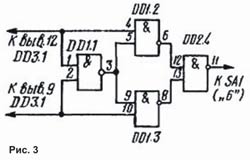
The controls of the machine - switches, a variable resistor and a power supply switch (it is not on the diagram) are mounted on the front wall of the case in which the chassis is installed. Clamps are attached to the back wall (they are also not shown in the diagram) or connectors for connecting garlands. In the absence of the K155LE1 microcircuit, you can do without it altogether by abandoning the "complex" garland ignition program (position "6" of the SA1 switch), or assemble this machine assembly on the K155LAZ microcircuit according to the one shown in Fig. 3 scheme. The node will be greatly simplified if one of the elements of the K155LP5 chip is used in it. In this case, pin 3 of the microcircuit is connected to pin "6" of switch SA1, and pins 1 and 2, respectively, to pins 12 and 9 of the DD3.1 chip. Naturally, pins 7 and 14 of the microcircuit must be connected to the power source. In any version of the new version of the node, you will have to slightly change the print pattern on the board.
The machine does not require adjustment, but for reliable switching of garlands, it may be necessary to reduce the resistance of the resistors in the control electrode circuit of the trinistors to 200 ohms. If you want to change the switching frequency, you should select resistors R 1, R 2 and capacitor C1. Author: O.Zhelyuk, Kostopol; Publication: cxem.net
Energy from space for Starship
08.05.2024 New method for creating powerful batteries
08.05.2024 Alcohol content of warm beer
07.05.2024
▪ Liquid cooling system for XMG Oasis Mk2 laptops ▪ 20-core Apple M1 Ultra processor ▪ Remote shutdown of car engines ▪ Navigator looking for parking
▪ section of the site Fundamentals of safe life (OBZhD). Article selection ▪ article by Jean-Paul Sartre. Famous aphorisms ▪ article Arrow indicators. Encyclopedia of radio electronics and electrical engineering
Comments on the article: Dimych I assembled this circuit in the early 90s, everything worked right away, this circuit was in the magazine "To Help the Radio Amateur"
Home page | Library | Articles | Website map | Site Reviews
www.diagram.com.ua |


 Leave your comment on this article: