Color and music installation. Encyclopedia of radio electronics and electrical engineering

Encyclopedia of radio electronics and electrical engineering / Color and music installations, garlands
 Comments on the article
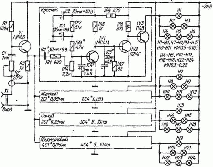
The principle of operation of the installation is based on the separation of the spectrum of the audio signal by frequency.
(click to enlarge)
To achieve greater diversity and richness of the color pattern, instead of the widespread three-color system, it uses a four-color system (red, yellow, blue and purple). The spectrum of the input signal is distributed between the channels approximately as follows: red - up to 400 Hz, yellow - 400..3000 Hz, blue - 3000-6000 Hz, violet - above 6000 Hz. Connect the unit directly to the output of the AF amplifier in parallel with the loudspeaker.
The audio frequency signal enters the installation channels through an emitter follower on transistor V1. The signal level is regulated by a variable resistor R2. All four channels are identical in circuit and differ only in the values of the capacitors of the frequency-selective circuits (capacitors of small capacity ZC4 and 4C4 may not be required, since the parasitic capacitance of the installation is approximately the same). Variable resistors 1R4-4R4 are designed for the main control of the signal level separately in each channel. This allows you to choose the optimal color saturation in the channels, and also, if necessary, create a constant illumination (background) of the desired color at low signals and in pauses.
Band signal amplifiers are assembled on three transistors. Two of them (in the "red" channel 1V1, 1V2) work in the pre-amplification stages, the third (1V3) - in the output stage. Amplifier loads are HI-H24 incandescent lamps. The use of lamps for different voltages in each channel made it possible to obtain a smooth> change in the brightness of the glow with sharp changes in the signal. The combination of lamps indicated in the diagram provides, at low input signal levels, the reproduction of a color background obtained due to the weak glow of lamps with high inertia (H4-H6, H10-H12, etc.) and at the same time a sharp increase in brightness during strong flashes of the input signal due to the lamps H1-H3, H7-H9 and others, which flash in this case with overheating (due to the short duration of the flashes, this is not dangerous).
The unit is powered from the AC mains through a stabilized rectifier that provides an output voltage of 26 ... 30 V at a load current of 4 ... 5 A.
During installation, the transistors of the terminal and output stages (1V2, 1V3, 2V2, 2V3, etc.) must be installed on heat sinks with an effective cooling surface area of at least 300 cm2.
Establishing the installation comes down to selecting resistors for the bias circuits of the first stages of preamplifiers (1R3, 2R3, etc.) at the start of ignition of the lamps with a minimum signal at the input and to selecting capacitors for frequency-setting circuits so that the bands of adjacent channels overlap somewhat.
 See other articles Section Color and music installations, garlands.
Read and write useful comments on this article.
<< Back
 Latest news of science and technology, new electronics:
Energy from space for Starship
08.05.2024
Producing solar energy in space is becoming more feasible with the advent of new technologies and the development of space programs. The head of the startup Virtus Solis shared his vision of using SpaceX's Starship to create orbital power plants capable of powering the Earth. Startup Virtus Solis has unveiled an ambitious project to create orbital power plants using SpaceX's Starship. This idea could significantly change the field of solar energy production, making it more accessible and cheaper. The core of the startup's plan is to reduce the cost of launching satellites into space using Starship. This technological breakthrough is expected to make solar energy production in space more competitive with traditional energy sources. Virtual Solis plans to build large photovoltaic panels in orbit, using Starship to deliver the necessary equipment. However, one of the key challenges ... >>
New method for creating powerful batteries
08.05.2024
With the development of technology and the expanding use of electronics, the issue of creating efficient and safe energy sources is becoming increasingly urgent. Researchers at the University of Queensland have unveiled a new approach to creating high-power zinc-based batteries that could change the landscape of the energy industry. One of the main problems with traditional water-based rechargeable batteries was their low voltage, which limited their use in modern devices. But thanks to a new method developed by scientists, this drawback has been successfully overcome. As part of their research, scientists turned to a special organic compound - catechol. It turned out to be an important component that can improve battery stability and increase its efficiency. This approach has led to a significant increase in the voltage of zinc-ion batteries, making them more competitive. According to scientists, such batteries have several advantages. They have b ... >>
Alcohol content of warm beer
07.05.2024
Beer, as one of the most common alcoholic drinks, has its own unique taste, which can change depending on the temperature of consumption. A new study by an international team of scientists has found that beer temperature has a significant impact on the perception of alcoholic taste. The study, led by materials scientist Lei Jiang, found that at different temperatures, ethanol and water molecules form different types of clusters, which affects the perception of alcoholic taste. At low temperatures, more pyramid-like clusters form, which reduces the pungency of the "ethanol" taste and makes the drink taste less alcoholic. On the contrary, as the temperature increases, the clusters become more chain-like, resulting in a more pronounced alcoholic taste. This explains why the taste of some alcoholic drinks, such as baijiu, can change depending on temperature. The data obtained opens up new prospects for beverage manufacturers, ... >>
| Random news from the Archive Hybrid iron with vacuum cleaner
01.03.2003
In England, an iron has been patented, which can be used to iron clothes hanging vertically in the wardrobe.
The built-in fan sucks fabric to an iron soleplate. Vacuum pressure improves the quality of ironing when using a new iron and in the usual way, on an ironing board. Release is expected to begin this year.
|
Other interesting news:
▪ IGBT Modules for Three Level UPS Inverters
▪ Thought controls the genes
▪ superionic ice
▪ Clean energy overtakes coal
▪ Toshiba TC3567CFSG and TC3567DFSG wearable ICs
News feed of science and technology, new electronics
 Interesting materials of the Free Technical Library:
▪ site section Lighting. Article selection
▪ article Fire table. Tips for the home master
▪ article What is acid rain? Detailed answer
▪ article Nut Gynds. Legends, cultivation, methods of application
▪ article Advantages of electronic transformers for halogen lamps. Encyclopedia of radio electronics and electrical engineering
▪ Article Six matching numbers. Focus Secret
Leave your comment on this article:
 All languages of this page
Home page | Library | Articles | Website map | Site Reviews

www.diagram.com.ua
2000-2024


 Arabic
 Bengali
 Chinese
 English
 French
 German
 Hebrew
 Hindi
Hindi Italian
 Japanese
 Korean
 Malay
Malay Polish
 Portuguese
 Spanish
 Turkish
 Ukrainian
 Vietnamese