|
|


 Arabic
 Bengali
 Chinese
 English
 French
 German
 Hebrew
 Hindi
Hindi Italian
 Japanese
 Korean
 Malay
Malay Polish
 Portuguese
 Spanish
 Turkish
 Ukrainian
 Vietnamese
|
ENCYCLOPEDIA OF RADIO ELECTRONICS AND ELECTRICAL ENGINEERING Transistor converter at 144 MHz. Encyclopedia of radio electronics and electrical engineering
Encyclopedia of radio electronics and electrical engineering / radio reception The current requirements for receiving sports VHF equipment are quite contradictory. To achieve maximum sensitivity, it is necessary to ensure that the noise figure is as low as possible. At the same time, the receiver must have a wide dynamic range and low crosstalk to be able to handle interfering signals from nearby powerful radios. That's why. on the one hand, one should not strive to obtain a large RF gain, on the other hand, the gain should be such that the proportion of noise introduced by the mixer into the total noise figure is negligible. Gain control by changing the emitter current of the RF amplifier and mixer cannot be introduced, because the lowest cross-distortion coefficient corresponds to a strictly defined emitter current. Apparently, to improve the characteristics of the RF amplifier, it is advisable to use an attenuator at the input. As for the noise introduced by the local oscillator, in order to reduce them, it is desirable to perform the mixer according to a balanced circuit. Satisfactory results can also be obtained with a transistor mixer by choosing a relatively high IF value and well filtering out the harmonic components of the local oscillator voltage. When using a quartz-stabilized local oscillator, it is advisable to excite quartz at the highest possible mechanical harmonics, rather than isolating the required harmonic from the frequency spectrum. Taking into account these requirements, a transistor converter was made with satisfactory electrical parameters. It is designed to receive signals from radio stations in the 144 MHz band. Its intermediate frequency is 28-30 MHz. The converter is simple and accessible for repetition by a radio amateur of average qualification. The converter is powered by a stabilized source. Current consumption - about 15 mA. The noise factor of the converter does not exceed 3-3,5. who.
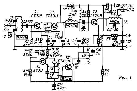
The converter circuit is shown in fig. 1. The lowest noise figure is achieved by matching the resistances of the signal source and the converter input. Therefore, the input is made according to the so-called "scheme with a capacitive tap". The use of a high-frequency low-noise transistor T1 of the GT329 type made it possible to make an RF amplifier according to a cascode circuit that provides a high stable gain without the use of neutralization. It is also possible to use transistors GT311 (or GT313). In this case, it is advisable to perform the first stage according to the scheme of a resonant RF amplifier with a common emitter, using neutralization. The output capacitance of the transistor T2, the capacitance of the trimmer capacitor C6. the inductance of the coil L2, the input capacitance of the transistor T3 and the capacitance of the capacitor C7 form an interstage matching P-filter. Thus, the current principle of constructing a resonant RF amplifier is implemented. A converter mixer is assembled on transistor T3. The amplified signal voltage is applied to its base circuit, and the local oscillator voltage is applied to the emitter circuit. The collector circuit includes a broadband circuit L3C10, tuned to a frequency of 29 MHz. Table 1
The IF signal voltage is taken from the coupling coil L4. Converter local oscillator - two-stage. On transistor T4, a master oscillator is assembled according to a "three-point" circuit with quartz in a positive feedback circuit. Quartz Pe1 is excited at the fifth mechanical harmonic. The L5C13 circuit in the collector circuit of the T4 transistor is tuned to a frequency of 58 MHz. You can also use quartz with a frequency of 8286 kHz. exciting it on the seventh mechanical harmonic, or 6444 kHz - on the ninth. In this case, however, it is necessary to use inductive compensation for the static capacitance of quartz. A coil is connected in parallel to the quartz, which, together with the capacitance of the quartz holder and the static capacitance of the quartz, forms a circuit tuned to a frequency of 58 MHz. This inclusion makes it easy to excite resonators at higher mechanical harmonics. A frequency doubler is assembled on the T5 transistor. The converter is mounted on a chassis measuring 85x45x20 mm, made of silver-plated brass sheet 0,5 mm thick. The chassis is separated by a Z-shaped partition separating the input circuit of the RF amplifier from the output circuit and from the local oscillator. The installation was carried out by a hinged method in compliance with the specifics of the installation of VHF equipment. Particular attention must be paid to the minimum length of the leads of transistors and bypass capacitors. The tuning core of the L3 coil is ferrite, the L5, L6 coils are brass. Trimmer capacitors can be used to tune coils instead of cores. Coil data are summarized in a table. When setting up the converter, the collector currents are set for transistors 77, T2 equal to 3,5, for T3 - 3-3,5 for T4 2,5-3 mA. The collector current of the transistor T5 depends on the excitation voltage. It is installed by selecting a tap from the L5 coil, to which the base of the T5 transistor is connected. Author: L. Rud (RB5LCE), Izyum, Kharkiv region; Publication: N. Bolshakov, rf.atnn.ru
Artificial leather for touch emulation
15.04.2024 Petgugu Global cat litter
15.04.2024 The attractiveness of caring men
14.04.2024
▪ People hunt birds or vice versa ▪ Video club for Japanese pensioners
▪ section of the website Audiotechnics. Article selection ▪ article Every nation has the government it deserves. Popular expression ▪ Article Pediatrician. Job description
Home page | Library | Articles | Website map | Site Reviews
www.diagram.com.ua |

 Leave your comment on this article: