|
|


 Arabic
 Bengali
 Chinese
 English
 French
 German
 Hebrew
 Hindi
Hindi Italian
 Japanese
 Korean
 Malay
Malay Polish
 Portuguese
 Spanish
 Turkish
 Ukrainian
 Vietnamese
|
ENCYCLOPEDIA OF RADIO ELECTRONICS AND ELECTRICAL ENGINEERING Theory and practice of the phase inverter. Encyclopedia of radio electronics and electrical engineering
Encyclopedia of radio electronics and electrical engineering / Speakers The article by an Italian acoustician reproduced here with the blessing of the author was originally entitled Teoria e pratica del condotto di accordo. That is, in literal translation - "Theory and practice of a phase inverter." This title, in our opinion, corresponded to the content of the article only formally. Indeed, we are talking about the relationship between the simplest theoretical model of a phase inverter and those surprises that practice is preparing. But this - if formally and superficially. But in essence, the article contains an answer to questions that arise, judging by the editorial mail, all the time when calculating and manufacturing a phase inverter subwoofer. Question one: "If you calculate a phase inverter using a formula that has been known for a long time, will the finished phase inverter have the calculated frequency?" Our Italian colleague, who has eaten about a dozen dogs in his life on phase inverters, replies: "No, it will not work." And then he explains why and, most importantly, how much it will not work. Question two: "I calculated the tunnel, but it is so long that it does not fit anywhere. How to be?" And here the signor offers such original solutions that it is precisely this side of his work that we put in the headline. So the key word in the new heading should be understood not in the new Russian way (otherwise we would have written: "in short - a phase inverter"), but quite literally. Geometrically. And now Signor Matarazzo has the floor to speak. Phase inverter: in short!
Fig 1. Diagram of a Helmholtz resonator. That from which everything comes.
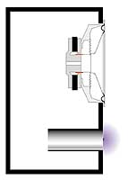
Fig 2. The classic design of the phase inverter. In this case, the influence of the wall is often not taken into account.
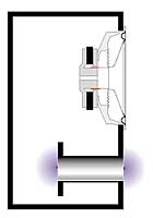
Fig 3. Phase inverter with a tunnel, the ends of which are in free space. There is no wall effect here.
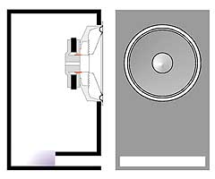
Fig 4. You can bring the tunnel completely out. Here again there will be a "virtual elongation".
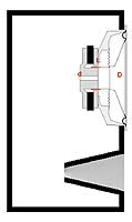
Figure 5. You can get a "virtual extension" at both ends of the tunnel by making another flange.
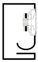
Figure 6. Slot tunnel located far from the walls of the box.
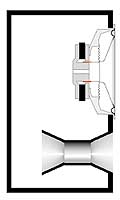
Figure 7. Slot tunnel located near the wall. As a result of the influence of the wall, its "acoustic" length is greater than the geometric one.
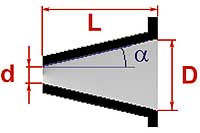
Figure 8. Tunnel in the form of a truncated cone.
Figure 9. The main dimensions of the conical tunnel.
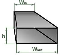
Figure 10. Dimensions of the slotted version of the conical tunnel.
Fig 11. Exponential tunnel.
Figure 12. Tunnel in the shape of an hourglass.
Figure 13. The main dimensions of the tunnel in the form of an hourglass.
Figure 14. Slotted version of the hourglass. Magic formulas One of the most common wishes in the author's e-mail is to give a "magic formula" by which an ACS reader could calculate the phase inverter himself. This is, in principle, not difficult. The phase inverter is one of the implementations of a device called the "Helmholtz resonator". The formula for its calculation is not much more complicated than the most common and accessible model of such a resonator. An empty Coca-Cola bottle (only a bottle, not an aluminum can) is just such a resonator, tuned to a frequency of 185 Hz, this has been verified. However, the Helmholtz resonator is much older than even this packaging of a popular drink, which is gradually becoming obsolete. However, the classical scheme of the Helmholtz resonator is similar to a bottle (Fig. 1). In order for such a resonator to work, it is important that it has a volume V and a tunnel with a cross-sectional area S and a length L. Knowing this, the tuning frequency of the Helmholtz resonator (or phase inverter, which is the same thing) can now be calculated by the formula:
where Fb is the tuning frequency in Hz, s is the speed of sound equal to 344 m/s, S is the area of the tunnel in sq. m, L is the length of the tunnel in m, V is the volume of the box in cubic meters. m. This formula is really magical, in the sense that the bass reflex setting does not depend on the parameters of the speaker that will be installed in it. The volume of the box and the dimensions of the tunnel determine the frequency of tuning once and for all. Everything seemed to be done. Let's get started. Suppose we have a box with a volume of 50 liters. We want to turn it into a bass reflex box tuned to 50Hz. It was decided to make the tunnel diameter 8 cm. According to the formula just given, the tuning frequency of 50 Hz will be obtained if the length of the tunnel is 12,05 cm. We carefully manufacture all the parts, assemble them into a structure, as in fig. 2, and for verification we measure the actually resulting resonant frequency of the phase inverter. And we see, to our surprise, that it is not 50 Hz, as it should be according to the formula, but 41 Hz. What's wrong and where did we go wrong? Yes, nowhere. Our freshly built phase inverter would be tuned to a frequency close to that obtained by the Helmholtz formula if it were made, as shown in Fig. 3. This case is closest to the ideal model described by the formula: here both ends of the tunnel "hang in the air", relatively far from any obstacles. In our design, one of the ends of the tunnel mates with the wall of the box. For the air oscillating in the tunnel, this is not indifferent, because of the influence of the "flange" at the end of the tunnel, it seems to be its virtual elongation. The phase inverter will be configured as if the length of the tunnel was 18 cm, and not 12, as it really is. Note that the same thing will happen if the tunnel is completely placed outside the box, again aligning one of its ends with the wall (Fig. 4). There is an empirical dependence of the "virtual elongation" of the tunnel depending on its dimensions. For a circular tunnel, one cut of which is located far enough from the walls of the box (or other obstacles), and the other is in the plane of the wall, this elongation is approximately equal to 0,85D. Now, if we substitute all the constants into the Helmholtz formula, introduce a correction for "virtual elongation", and express all dimensions in familiar units, the final formula for the length of the tunnel with a diameter D, which ensures that a box of volume V is tuned to a frequency Fb, will look like this:
Here the frequency is in hertz, the volume is in liters, and the length and diameter of the tunnel are in millimeters, as we are used to. The result obtained is valuable not only because it allows at the calculation stage to obtain a length value close to the final one, giving the required value of the tuning frequency, but also because it opens up certain reserves for shortening the tunnel. We have already won almost one diameter. It is possible to shorten the tunnel even further while maintaining the same tuning frequency by making flanges at both ends, as shown in fig. 5. Now, everything seems to be taken into account, and, armed with this formula, we seem to be omnipotent. This is where we face difficulties. First difficulties The first (and main) difficulty is as follows: if a relatively small box needs to be tuned to a fairly low frequency, then by substituting a large diameter into the formula for the length of the tunnel, we will get a large length. Let's try to substitute a smaller diameter - and everything turns out fine. A large diameter requires a large length, and a small one just needs a small one. What's wrong with that? And here's what. Moving, the speaker cone with its back side "pushes" practically incompressible air through the phase inverter tunnel. Since the volume of oscillating air is constant, the air velocity in the tunnel will be as many times greater than the oscillatory velocity of the diffuser, as many times the tunnel cross-sectional area is less than the diffuser area. If you make a tunnel ten times smaller than a diffuser, the flow velocity in it will be high, and when it reaches 25 - 27 meters per second, turbulence and jet noise will inevitably appear. The great researcher of acoustic systems R. Small showed that the minimum section of the tunnel depends on the diameter of the speaker, the largest stroke of its cone and the tuning frequency of the phase inverter. Small came up with a completely empirical but working formula for calculating the minimum size of a tunnel:
Small derived his formula in units familiar to him, so that the speaker diameter Ds, the maximum cone travel Xmax and the minimum tunnel diameter Dmin are expressed in inches. The tuning frequency of the phase inverter is, as usual, in hertz. Now things don't look as rosy as before. It often turns out that if you choose the right diameter of the tunnel, it comes out incredibly long. And if you reduce the diameter, there is a chance that the tunnel will "whistle" even at medium power. In addition to jet noise proper, tunnels of small diameter also have a tendency to so-called "organ resonances", the frequency of which is much higher than the tuning frequency of the phase inverter and which are excited in the tunnel by turbulences at high flow rates. Faced with this dilemma, ACS readers usually call the editor and ask for a solution. I have three of them: easy, medium and extreme. A simple solution for small problems When the estimated length of the tunnel is such that it almost fits in the hull and only slightly shortens its length with the same setting and cross-sectional area, I recommend using a slotted tunnel instead of a round one, and placing it not in the middle of the front wall of the hull (as in Fig. 6 ), but close to one of the side walls (as in Fig. 7). Then, at the end of the tunnel, located inside the box, the effect of "virtual elongation" will be affected due to the wall located next to it. Experiments show that with a constant cross-sectional area and tuning frequency, the tunnel shown in Fig. 7 is about 15% shorter than with the construction as in fig. 6. A slotted phase inverter, in principle, is less prone to organ resonances than a round one, but to protect yourself even more, I recommend installing sound-absorbing elements inside the tunnel, in the form of narrow strips of felt glued to the inner surface of the tunnel in the region of a third of its length. This is a simple solution. If it is not enough, you will have to go to the average. Medium solution for bigger problems An intermediate complexity solution is to use a truncated cone tunnel, as in Fig. 8. My experiments with such tunnels have shown that here it is possible to reduce the cross-sectional area of the inlet compared to the minimum allowable according to the Small formula without the danger of jet noise. In addition, a conical tunnel is much less prone to organ resonances than a cylindrical one. In 1995 I wrote a program for calculating conical tunnels. It replaces a conical tunnel with a sequence of cylindrical ones and, by successive approximations, calculates the length required to replace a regular constant section tunnel. This program is made for everyone, and it can be downloaded from the ACS magazine website audiocarstereo.it/ in the ACS Software section. A small program that runs under DOS, you can download and calculate it yourself. And you can do it differently. When preparing the Russian edition of this article, the results of calculations using the CONICO program were summarized in a table, from which you can take the finished version. The table is compiled for a tunnel with a diameter of 80 mm. This diameter value is suitable for most subwoofers with a cone diameter of 250 mm. After calculating the required length of the tunnel using the formula, find this value in the first column. For example, according to your calculations, it turned out that you need a tunnel 400 mm long, for example, to tune a box with a volume of 30 liters to a frequency of 33 Hz. The project is not trivial, and it will not be easy to place such a tunnel inside such a box. Now look at the next three columns. It shows the dimensions of the equivalent conical tunnel calculated by the program, the length of which will no longer be 400, but only 250 mm. Quite another matter. What the dimensions in the table mean is shown in fig. 9.
Table 2 is compiled for the initial tunnel with a diameter of 100 mm. This will fit most subwoofers with a 300mm driver. If you decide to use the program yourself, remember: a truncated cone-shaped tunnel is made with an inclination angle of the generatrix a from 2 to 4 degrees. This angle of more than 6 - 8 degrees is not recommended, in this case, turbulence and jet noise may occur at the inlet (narrow) end of the tunnel. However, even with a small taper, the reduction in the length of the tunnel is quite significant. A tunnel in the form of a truncated cone does not have to have a circular cross section. Like a regular, cylindrical one, it is sometimes more convenient to make it in the form of a slotted one. Even, as a rule, it is more convenient, because then it is assembled from flat parts. The dimensions of the slotted version of the conical tunnel are given in the following columns of the table, and what these dimensions mean is shown in fig. 10. Replacing a conventional tunnel with a conical one can solve many problems. But not all. Sometimes the length of the tunnel turns out to be so large that even shortening it by 30 - 35% is not enough. For these difficult cases... ...an extreme solution for big problems An extreme solution is to use a tunnel with exponential contours, as shown in Fig. 11. For such a tunnel, the cross-sectional area first gradually decreases, and then just as smoothly increases to the maximum. From the point of view of compactness for a given tuning frequency, resistance to jet noise and organ resonances, the exponential tunnel has no equal. But it has no equal in terms of manufacturing complexity, even if its contours are calculated according to the same principle as was done in the case of a conical tunnel. In order to still be able to take advantage of the exponential tunnel in practice, I came up with its modification: the tunnel, which I called the "hourglass" (Fig. 12). The hourglass tunnel consists of a cylindrical section and two conical ones, hence the outward resemblance to an ancient instrument for measuring time. This geometry makes it possible to shorten the tunnel compared to the original, constant section, at least one and a half times, or even more. To calculate the hourglass, I also wrote a program, it can be found there, on the ACS website. And just like for a conical tunnel, here is a table with ready-made calculation options.
What the dimensions in tables 3 and 4 mean will become clear from fig. 13. D and d are the diameter of the cylindrical section and the largest diameter of the conical section, respectively, L1 and L2 are the lengths of the sections. Lmax is the total length of the hourglass tunnel, just for comparison, how much shorter it was made, but in general, this is L1 + 2L2. Technologically, making an hourglass with a circular cross section is not always easy and convenient. Therefore, here it can also be made in the form of a profiled slot, it will turn out, as in Fig. 14. To replace a tunnel with a diameter of 80 mm, I recommend choosing a slot height of 50 mm, and for replacing a 100 mm cylindrical tunnel - equal to 60 mm. Then the width of the section of a constant section Wmin and the maximum width at the entrance and exit of the tunnel Wmax will be the same as in the table (the lengths of the sections L1 and L2 - as in the case of a circular section, nothing changes here). If necessary, the slot tunnel height h can be changed by simultaneously adjusting both Wmin and Wmax so that the values of the cross-sectional area (h.Wmin, h.Wmax) remain unchanged. I used the hourglass tunnel variant of the phase inverter, for example, when I was making a home theater subwoofer with a tuning frequency of 17 Hz. The estimated length of the tunnel turned out to be more than a meter, and by calculating the "hourglass", I was able to reduce it by almost half, while there was no noise even at a power of about 100 watts. Hope this helps you too... About the author: Jean-Pierro Matarazzo was born in 1953 in Avellino, Italy. Since the early 70s he has been working in the field of professional acoustics. For many years he was responsible for testing acoustic systems for the magazine "Suono" ("Sound"). In the 90s, he developed a number of new mathematical models of the process of sound emission by loudspeaker diffusers and several projects of acoustic systems for industry, including the Opera model, popular in Italy. Since the late 90s, he has been actively collaborating with the magazines "Audio Review", "Digital Video" and, most importantly for us, "ACS" ("Audio Car Stereo"). In all three, he is in charge of measuring parameters and testing acoustics. What else?. Married. Two sons are growing, 7 years old and 10. Author: Jean-Pierro Matarazzo. Translation from Italian by E. Zhurkova; Publication: cxem.net
Artificial leather for touch emulation
15.04.2024 Petgugu Global cat litter
15.04.2024 The attractiveness of caring men
14.04.2024
▪ Humanoid robots are already on sale ▪ Invented fabric that mosquitoes won't bite through ▪ Sony Ericsson LiveView Accessory ▪ Shoes with GPS will tell you the route
▪ section of the site for the Musician. Selection of articles ▪ article Air-hydraulic rocket plane. Tips for a modeller ▪ article Which European country has been at war with Japan for over a century? Detailed answer ▪ article Leersia rice-like. Legends, cultivation, methods of application ▪ article What is DIGITAL? Encyclopedia of radio electronics and electrical engineering ▪ article Spiral UHF antenna. Encyclopedia of radio electronics and electrical engineering
Home page | Library | Articles | Website map | Site Reviews
www.diagram.com.ua |


 = 3,14, that goes without saying.


 Leave your comment on this article: