|
|


 Arabic
 Bengali
 Chinese
 English
 French
 German
 Hebrew
 Hindi
Hindi Italian
 Japanese
 Korean
 Malay
Malay Polish
 Portuguese
 Spanish
 Turkish
 Ukrainian
 Vietnamese
|
ENCYCLOPEDIA OF RADIO ELECTRONICS AND ELECTRICAL ENGINEERING Hummingbird radio. Encyclopedia of radio electronics and electrical engineering
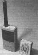
Encyclopedia of radio electronics and electrical engineering / Civil radio communications At present, the range of CB radio stations offered by trade enterprises seems to be ready to satisfy almost any user request. And yet they are not always satisfied with either the cost-effectiveness of the equipment, or its dimensions, weight, and price. The readers are offered a brief description of the radio station "Hummingbird", made on the basis of surface-mounted elements. You can make it yourself using conventional elements, you just have to re-design the printed circuit board (in this case, the dimensions of the radio station will increase). By replacing the quartz resonators, you will also make this radio station for the 28 MHz amateur band. The simplicity of the circuit solutions of the proposed design, the use of modern imported microcircuits and the use of surface-mounted radio elements make it possible to assemble the radio station on a single printed circuit board measuring only 45x50 mm, while achieving quite acceptable technical characteristics. And let "Kolibri" does not strike the imagination of future owners with the number of functions performed by it and the forced power of the transmitter, they will be able to appreciate the dimensions of the radio station, its economy and relatively low price. We have no doubt that this radio station will find its application for communication within the office or with car radio stations over short distances, as well as for communication from home with children walking on the street or during outdoor recreation.
"Hummingbird" is designed to work on one of the CBS channels in the narrowband frequency modulation mode. According to the main electrical parameters, the station corresponds to the list of typical characteristics of the 27 MHz band equipment. The operating frequencies of the receiver and transmitter are set by quartz resonators. The power is supplied from a battery of batteries or galvanic cells with a voltage of 3 ... more than 6 mA. The transmitter power at a supply voltage of 4,5 V is 200 mW, the maximum frequency deviation is -1,8 kHz. The sensitivity of the receiver is not worse than 0,3 μV, the power of the audio signal on the dynamic head with a resistance of 8 ohms is not less than 60 mW. The communication range between two Hummingbird radio stations can be 1 km, and with efficient stationary antennas - much more. The time of continuous operation powered by batteries with a capacity of 0,6 Ah is about 20 hours at a ratio of reception / transmission of 4:1. This characteristic corresponds to a fairly intense connection! The diagram of the radio station is shown in the figure. The signal from the antenna through the coupling capacitor C1 and the button SB1 is fed to the input of the high-frequency amplifier of the receiver (transistor VT1). The input L4C7C8 and output L5C13C14 amplifier circuits are tuned to the operating frequency.
Chip DA2 performs the functions of conversion, amplification of the intermediate frequency signal, frequency detection and noise suppressor. The local oscillator frequency is stabilized by a ZQ2 quartz resonator operating at the third mechanical harmonic. The intermediate frequency of 465 kHz obtained as a result of the conversion is enhanced by the IF and filtered by the piezoceramic filter Z1. The signal then passes through a limiting amplifier and is fed to a frequency detector. To detect the FM signal, an L10C32 circuit is connected to the microcircuit, which determines the tuning frequency, and the resistor R19 determines the bandwidth of the frequency detector. For normal operation of the detector, the circuit must be tuned to an intermediate frequency of 465 kHz and have a bandwidth of about 10 kHz. Through the low-pass filter R21C33, the low-frequency signal from pin 9 of the DA2 chip is fed to a low-frequency amplifier (DA3 chip). With the help of this microcircuit, the frequency correction of the signal and its amplification up to 60 ... 100 mW are carried out. The receiver noise suppressor is implemented on the op-amp and the threshold device, which are part of the DA2 chip. The demodulated signal from the output of the FM detector is fed to a narrow-band filter with a maximum transmission coefficient at frequencies of 8...10 kHz. The filter does not pass the speech signal in the 300 ... 3000 Hz band, but selects and amplifies the noise in the 8 ... 10 kHz frequency band, which are rectified by the amplitude detector on the VD1 diode. If the rectified voltage is greater than the threshold of the threshold device, a high level occurs at pin 13 of the DA2 microcircuit, which turns off the low-frequency amplifier (while the DA3 microcircuit consumes less than 60 μA). The response voltage of the threshold device is regulated by resistor R14. When you press the SB1 button, the antenna and battery are connected to the transmitter. L2 choke is used for high frequency decoupling. The transmitter is made on a DA1 chip, which contains a microphone amplifier-limiter, a master oscillator, a frequency modulator and other elements. Transistor VT2 amplifies the RF signal in terms of power. The C34L12C38 P-loop matches the output impedance of the amplifier with the input impedance of the antenna, and also filters the output signal of the radio station. The signal from the electret microphone BM1 is amplified by a microphone amplifier (MU) and fed to the FM modulator. Using the L3 coil trimmer, the operating frequency of the transmitter is set. The generated and amplified RF signal from pin 14 of the DA1 microcircuit is fed to a frequency multiplier by two, the function of which is performed by one of the transistors of the microcircuit. The load of the frequency multiplier is the circuit L7C19C20. Further, the signal is amplified by the second transistor of the microcircuit, from the collector circuit L8C29C30 of which the signal is fed to the output transistor VT2 of the transmitter. Transistor VT2 operates in mode C. In the radio station, oxide capacitors K50-35 or K50-40 are applicable. Resistor R10 - SPZ-38a. Intermediate frequency filter Z1 - type FP1P1-60.02. Toggle switch SA1 - PD9-2, button SB1 -MP7. Quartz resonators ZQ1 and ZQ2 set the tuning frequency of the radio station. Their frequencies are determined as follows: the frequency ZQ1 must be equal to Fwork / 2, and the frequency ZQ2 - Fwork - 465, where Fwork is the operating frequency of the radio station in kilohertz. The BM1 microphone can be used by MKE-332. Dynamic head BA1 - any resistance 8 ... 16 Ohm. Information about inductors is presented in table. 1. Coil L1 is not shown in the table, it is an integral part of the antenna. Antenna designs are detailed below.
Establishing a properly assembled radio station comes down to setting up the circuits. A 2 V power supply is connected to pins 3 and 4,5 of the board, observing the polarity, and a dynamic head is connected to pins 4 and 5. Turning on the radio station, measure the voltage across transistors and microcircuits with a DC voltmeter. The modes are given in table. 2. A strong difference from the specified values indicates a malfunction.
With a working receiving part, there are noises at pin 9 of the DA2 microcircuit, and with the noise suppressor turned off (the engine of the resistor R10 is in the left position according to the diagram), they are heard in the dynamic head. To set up a frequency detector, you need to apply a frequency-modulated signal with a frequency of 465 kHz with a deviation of 1,1 kHz from the signal generator to pin 5 of the DA2 chip. The FM detector is tuned with a software coil trimmer to the maximum of the demodulated signal at pin 9 of the D2 chip. Then, a signal with the tuning frequency of the radio station is fed to the receiver input from the high-frequency generator (the frequency deviation of the generator is set equal to 1,1 kHz). By gradually reducing the input signal level and adjusting the coils L4, L5, the maximum sensitivity of the receiver is achieved. Coils without a trimmer are tuned by compressing or stretching the turns. For the convenience of setting up such a coil, you can bring a ferrite or brass rod to it. If the best results are obtained when a brass trimmer is brought up, then the coil turns must be stretched, and if ferrite, the coil turns must be compressed. When setting up the transmitter, an equivalent load is connected to the antenna terminal 1 of the radio station, for example, a non-wire resistor with a resistance of about 50 ohms with a power of at least 0,25 watts. An oscilloscope is connected to the control point KT5, and in the transmission mode, the presence of a signal from the microphone is checked, the signal amplitude should be about 0,5 V. You can check the operation of the master oscillator by connecting a high-frequency voltmeter to the control points KT1 and KTZ. In transmission mode, the alternating voltage at these points should be 0,2 ... 0,3 V. At the same points, the frequency of the master oscillator is measured. Then the RF voltmeter is connected to the control point KT7 and, by rotating the L7 coil trimmer, the maximum readings of the voltmeter are achieved. Similarly, adjust the circuit L8C29C30, measuring the voltage at the point KT10. The RF voltage in KT7 and KT10 should be 0,6 and 1 V, respectively. It should be ensured that the voltage on the dummy load is about 3,2 V, which corresponds to a transmitter power of 200 mW. Maximum power is achieved by adjusting the L12 coil and refining the settings of the L7 and 18 coils. Complete the adjustment of the transmitter by setting the frequency deviation (1,8 kHz) resistor R9. To do this, you can use any CB radio station tuned to the working channel. The transmitted speech signal should not be subject to distortions that are noticeable to the ear. When setting up, it is desirable to control the current consumption of the transmitter, not allowing it to exceed more than 150 mA. The radio range largely depends on the antenna. It is known that one of the optimal is an antenna, the length of which is equal to a quarter of the length of the radio wave. For the 27 MHz band, a quarter wavelength is about 2,7 m. It is clear that such a length of a whip antenna in a wearable version is unacceptable. Then an antenna is used, the length of which is chosen from design considerations, and tuning to resonance is carried out by an "extension" coil. On the radio diagram, this is the L1 coil. Widely used designs of antennas with a pin made in the form of a spiral wound coil to coil or in increments. The helical antenna can be tuned to resonance by selecting the number of turns and the pitch of the helix. "Shortened" antennas have a narrow bandwidth and are very sensitive to nearby objects, but a more acceptable option is not known for a small radio station. For the manufacture of a spiral antenna, any rod or tube made of plastic, fiberglass, polyethylene or other insulating material is suitable. A wire is wound on the rod turn to turn or with a certain step, the ends of the wire are fixed on the rod. In table. 3 shows the data of some antenna options. The third version of the antenna was made on a ballpoint pen.
You can tune the antenna using the field strength indicator [1, 2]. The helical antenna is installed on the radio station, the "Transmit" mode is turned on and the field strength is estimated. By selecting the number of turns, the antenna is tuned according to the maximum reading of the device. The tuning accuracy will even depend on the method of fastening the wire and the material used (threads, heat-shrinkable tube, etc.). The telescopic antenna is tuned in a similar way, only the inductor (L1), which is connected in series with the pin, can serve as a tuning element. Literature
Authors:G. Minakov, M. Fedotov, Voronezh, D. Travinov, Moscow; Publication: N. Bolshakov, rf.atnn.ru
The world's tallest astronomical observatory opened
04.05.2024 Controlling objects using air currents
04.05.2024 Purebred dogs get sick no more often than purebred dogs
03.05.2024
▪ Ingenic tablet with Android 4.0 for $120 ▪ Data transmission over the mains
▪ site section Power supply. Article selection ▪ article White slaves. White blacks. Popular expression ▪ article What kind of music fascinates snakes the most? Detailed answer ▪ Article Security Specialist. Job description ▪ article Discoloration of ink and other dyes with activated carbon. Chemical experience
Home page | Library | Articles | Website map | Site Reviews
www.diagram.com.ua |


 Leave your comment on this article: