|
|


 Arabic
 Bengali
 Chinese
 English
 French
 German
 Hebrew
 Hindi
Hindi Italian
 Japanese
 Korean
 Malay
Malay Polish
 Portuguese
 Spanish
 Turkish
 Ukrainian
 Vietnamese
|
ENCYCLOPEDIA OF RADIO ELECTRONICS AND ELECTRICAL ENGINEERING Universal generator tester. Encyclopedia of radio electronics and electrical engineering
Encyclopedia of radio electronics and electrical engineering / Measuring technology Compact test signal generators are very popular with radio amateurs, useful in testing and setting up radio receiving and sound-reproducing equipment. We offer another design of such a generator, which is distinguished by an extended set of fixed frequencies. Industrial and home-made radio equipment contains 3H and IF paths, and IF frequencies have different values: 455 kHz in imported and 465 kHz in domestic AM signal receivers; 5,5, 6,5 and 10,7 MHz - in FM receivers. The journal "Radio" has already published circuits of probe generators for testing 3H and IF paths [1-3]. As a rule, they produce two signals - 3H and a modulated IF signal with one of the named frequencies. In order not to have to make several probes, the proposed generator provides for switching frequencies. It is suitable for testing almost any equipment, including the sound path of TVs. The scheme of the probe generator is shown in fig. one.
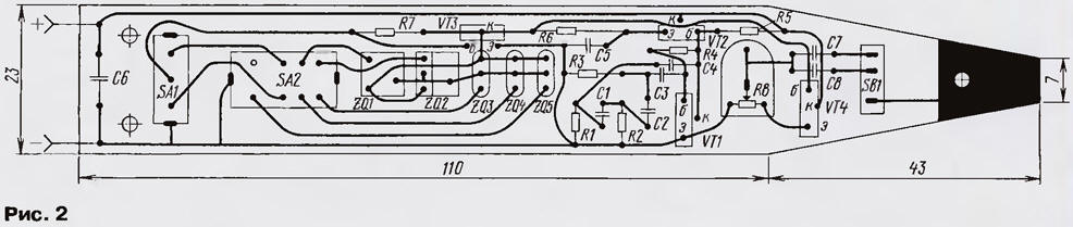
The audio frequency generator is assembled on a transistor VT1 according to a scheme with a phase-shifting RC circuit (capacitors C1 - C4 and resistors R1 - R3). The emitter follower on the transistor VT2 decouples the generator from the load - the RF generator. The latter is made on the transistor VT3. Instead of resonant LC circuits, the generator uses small-sized piezoceramic IF filters ZQ1 - ZQ5 from radios or TVs. The filter corresponding to the desired IF is selected by switches SA1 (FM or AM) and SA2 (specific IF value). In the 3H position, no filter is turned on and the RF generator is not working. In this case, only a 3H signal is output. The collector voltage of the RF generator changes in time with 3H oscillations, thus, the RF signal is modulated. In the switch positions "455" and "465" amplitude modulation occurs with a depth of 30...40%. In positions "5,5", "6,5" and "10,7", in addition to amplitude, there is also a parasitic frequency modulation, it is used when checking the paths of FM receivers. Parasitic FM is facilitated by the high generation frequency and wide bandwidth of piezo filters. The modulated RF signal is fed to the output emitter follower, assembled on the VT4 transistor, which significantly weakens the effect of the load (tested nodes) on the RF and 3H generators. Variable resistor R8 set the desired output level. Coupling capacitors C7 and C8 at the generator output are switched by the SB1 button. In the position of the switch SB1 shown in the diagram, only modulated RF signals pass through the relatively small capacitor C7. When the switches SA1 and SA2 are set to position "34", a large capacitor C1 is connected with the SB8 button. Power is supplied to the probe from the power circuits of the tested equipment. The supply voltage can range from 3 to 12 V. The probe generator is assembled on a board made of getinax or fiberglass. The location of parts and connecting conductors are shown in fig. 2. If the board is made of foil material, then a printed circuit board can also be made according to the drawing. After manufacturing, the board is placed in any suitable case, for example, from the GSP-1 grid field generator.
Transistors VT1 - VT4 can be replaced by KT3102 or KT312 with any letter index, it is desirable to select transistors VT2 and VT3 with the highest current transfer coefficient. For the RF generator, any piezoceramic filters from domestic or imported equipment with suitable frequencies are suitable. Switch SA1 applied type PD9-1, SA2 - PD21-2, button SB1 - MP-7 or other small. All resistors - MLT-0,125 (you can MLT-0,25), capacitors - KD, KM, K10 or other small ones. Resistor R8 - SPO-0,15 or SP-3-386. A needle soldered to the platform on the board (on the right in Fig. 1) is used as the output contact X2, and a wire is used as the X2 contact, at the end of which a crocodile clip is soldered. The establishment of a probe generator begins with the setting of the VT1 transistor mode. Its collector voltage should be 1,5 V at a supply voltage of 3 V. Resistor R4 is selected to set the collector voltage. After that, the presence of generation is checked when the supply voltage changes from 3 to 12 V. Then the capacitor C3 is soldered (the 3H generator stops working), the supply voltage is 3 V, and by selecting the resistor R7, high-frequency generation occurs at all fixed frequencies, i.e. when connecting any piezoceramic filter. If generation does not occur in any of the positions of the switches SA1 and SA2 (most often this happens in the "10,7" position), the resistor R6 is selected and then the operation of the RF generator is checked again at all frequencies. You can verify the presence of RF generation by connecting a high-frequency oscilloscope, a millivoltmeter, a simple detector with a measuring head, or a frequency meter to the output of the probe. In the latter case, the generation frequency is also checked at the same time. Then the capacitor C3 is replaced and, if there is an oscilloscope, the quality of the RF signal modulation is checked. Working with the probe is simple. If the 3H amplifier is being checked, the switches SA1 and SA2 are set to the "3H" position, the SB1 button is pressed and the 3H signal is applied with the X1 probe in turn to the various stages of the amplifier under test, while not forgetting to set the required signal level with resistor R8. When checking the IF of various equipment, the required frequency value is selected with the switches SA1 and SA2, the SB1 button is not pressed. Applying a signal to the input of the IF, first after the main selection filter, and then before it, they make sure that the signal passes through the filter and the IF. Otherwise, the IF is checked cascading. Literature
Author: A.Slinchenkov, Ozersk, Chelyabinsk region
Artificial leather for touch emulation
15.04.2024 Petgugu Global cat litter
15.04.2024 The attractiveness of caring men
14.04.2024
▪ Doubling the capacitance of supercapacitors
▪ section of the site for the Builder, home craftsman. Selection of articles ▪ article Shakespeare is not the main thing, but notes to it. Popular expression ▪ article Which athlete started training at 23 and won medals at the next Olympics? Detailed answer ▪ article Bear bow. Legends, cultivation, methods of application ▪ article Flowers and doves. Focus Secret
Comments on the article: Nicholas Very useful and necessary program - I wish you hello.
Home page | Library | Articles | Website map | Site Reviews
www.diagram.com.ua |


 Leave your comment on this article: