|
|


 Arabic
 Bengali
 Chinese
 English
 French
 German
 Hebrew
 Hindi
Hindi Italian
 Japanese
 Korean
 Malay
Malay Polish
 Portuguese
 Spanish
 Turkish
 Ukrainian
 Vietnamese
|
ENCYCLOPEDIA OF RADIO ELECTRONICS AND ELECTRICAL ENGINEERING Precision displacement meter. Encyclopedia of radio electronics and electrical engineering
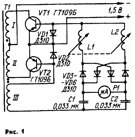
Encyclopedia of radio electronics and electrical engineering / Radio amateur designer One of the promising ways to create high-precision displacement control devices is to use inductive transducers with a digital readout of the measurement result. Known inductive linear displacement meters, in which, in order to increase the sensitivity, a phase-sensitive transistor detector is used. Such transducers have an increased transmission coefficient only near the equilibrium point of the measuring bridge, and in the rest of the measuring interval they are comparable in sensitivity to traditional devices. Displacement control devices are described, in which the sensor windings are included in a measuring bridge with ballast resistors. Such devices without fine tuning and optimization of the operating mode do not provide high accuracy and stability of the measurement results. Also known frequency inductive converters with windings included in the oscillatory circuit of the high frequency generator. The frequency of the output signal of such transducers is proportional to the measured displacement. Such devices also do not have advantages in sensitivity in comparison with others. At the Institute of Geotechnical Mechanics of the Academy of Sciences of the Ukrainian SSR, a simple inductive displacement meter has been developed and studied, which ensures high sensitivity, accuracy, and stability of the measurement results when the parameters of its elements change. Inductive displacement meter (see diagram in Fig. 1). contains a converter with differential windings L1, L2, a ring diode detector VD3-VD6, an output indicator P1, a rectangular voltage generator based on transistors VT1, VT2 and transformer T1.
Parallel circuits of serially connected differential windings L1, L2, an inductive sensor and capacitors C1, C2 of the measuring bridge are included in the positive feedback circuit of the generator. Such an inclusion automatically ensures the operation of the displacement transducer in resonant mode, that is, when the inductive resistance is compensated by the capacitive one and the total resistance of each circuit is practically equal to the active resistance of the windings. An alternating current flows through the measuring bridge, which is close to sinusoidal in shape, since the quality factor of the circuit is very high. Due to the presence of diodes VD1, VD2, the circuit current flows directly through the emitter junction of the generator transistor open in the corresponding half-cycle. The second transistor is closed at this time. The rectangular pulse generator operates almost without load, therefore, when it is started, the current in the circuit, starting from the very first cycle, reaches a steady value. Transistors operate without bias, which ensures their switching near the moment when the loop current "crosses zero", i.e., the converter operates in a resonant mode, in which the sensitivity of the displacement meter is maximum.
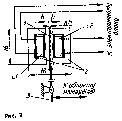
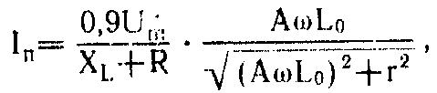
On fig. 2 schematically shows the design of the meter sensor itself. Coils L1 and L2 are placed on two W-shaped elements 2 of the magnetic circuit installed with a gap. In the gap between the elements there is an armature 1 made in the form of a plate of ferromagnetic material. The armature is mechanically connected by a rocker arm 3 to the moving link of the controlled mechanism. To determine the type of mathematical expression that determines the output current of the converter In, the necessary theoretical studies were carried out, as a result of which the following simplified formula was obtained:
In=(0,9Um/ХL+R) * (AwLo/(V(AwLo)2+r2)
Experimental studies of the transducer confirmed the validity of the obtained expression. To check the performance and technical characteristics of the inductance of the displacement meter, laboratory tests of several prototype samples were carried out in the complex of the microbarometer measuring system. It has been established that reliable start-up and stable operation of the generator are ensured at a power supply voltage of 0,3 V or more at temperatures ranging from -5 to +50 °C. Operation of the meter at lower temperatures has not been tested. The main factors that destabilize the operation of the converter are changes in the supply voltage and temperature. Therefore, the converter should be powered by a voltage stabilizer. The temperature error of the device in the range from +5...40°C does not exceed 5% for every 10°C, and there is no zero point shift, which is especially important when using a converter to indicate mismatch in compensating measuring systems.
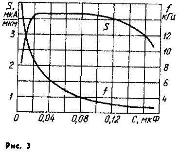
The sensitivity of the meter changes slightly when the capacitance of the measuring bridge capacitors changes in the range from 0,01 to 0,18 μF (Fig. 3). In this case, the resonant frequency is automatically set, determined by the parameters of the series LC circuits. The change in the inductance of each of the windings, caused by the movement of the armature in the working gap, does not exceed 10% of the nominal value. Since the displacement of the armature from the neutral position causes an increase in the inductance of one of the windings and a decrease in the inductance of the other by the same value, the resonant frequency remains practically unchanged. It depends very little on the supply voltage. The results of experimental studies show that when the supply voltage changes by 33%, the frequency drift does not exceed 0,25%. The described meter differs from the known ones in the simplicity of the device, efficiency, high metrological characteristics and is successfully used in high-precision microbarometers manufactured by the Riga experimental plant "Gidrometpribor". It can be used for precise displacement measurements in other areas of technology. Main technical characteristics:
The generator transformer T1 is wound on a Sh4x4 magnetic circuit made of 2000NM ferrite and contains three windings of 100 turns of PEV-1 0,12 wire. Coils L1, L2 of the sensor consist of 500 turns of wire PEV-1 0,12 each. The magnetic circuit of the sensor is two blocks Ш4х4 made of 2000NM ferrite. The P1 indicator is an M4205 microammeter with a total arrow deflection current of 30 μA and zero in the middle of the scale. Both parts of the magnetic circuit of the sensor with coils are attached to the base by means of special brackets with screws that allow you to change the size of the air gap. It is installed using calibrated plates. The sensor armature is made of permalloy and has a cross section of 5x0,3 mm. Almost any low-power transistors and diodes can be used in the converter. However, the use of silicon devices is associated with an increase in the voltage drop across p-n junctions, which requires an increase in the supply voltage. With denominations and types of elements. shown in the diagram in Fig. 1, the meter consumes a current of about 5 mA, and its sensitivity with an air gap of 2h=1 mm in the magnetic circuit of the sensor and a microammeter resistance of 0,5 kΩ is 3,5 μA/μm, which is almost ten times higher than the sensitivity of known sensors under equivalent initial conditions and meets the requirements for precision measurements of the movement of moving elements of barometric instruments. When using the described device in compensating measuring systems, it is not required to stabilize the supply voltage. Literature
Publication: N. Bolshakov, rf.atnn.ru
A New Way to Control and Manipulate Optical Signals
05.05.2024 Primium Seneca keyboard
05.05.2024 The world's tallest astronomical observatory opened
04.05.2024
▪ Unraveled the phenomenon of female instinct ▪ Vitamin B6 helps you remember dreams better ▪ Meizu Smart Button to Control Home Appliances ▪ Happiness from altruism is short-lived
▪ section of the site Firmware. Article selection ▪ article The pike was thrown into the river. Popular expression ▪ article What percentage of our brain do we use? Detailed answer ▪ article Elephant Grass. Legends, cultivation, methods of application ▪ article Imitator of bird voices. Encyclopedia of radio electronics and electrical engineering
Home page | Library | Articles | Website map | Site Reviews
www.diagram.com.ua |

 Leave your comment on this article: