|
|


 Arabic
 Bengali
 Chinese
 English
 French
 German
 Hebrew
 Hindi
Hindi Italian
 Japanese
 Korean
 Malay
Malay Polish
 Portuguese
 Spanish
 Turkish
 Ukrainian
 Vietnamese
|
ENCYCLOPEDIA OF RADIO ELECTRONICS AND ELECTRICAL ENGINEERING Photo flash with incandescent lamp . Encyclopedia of radio electronics and electrical engineering
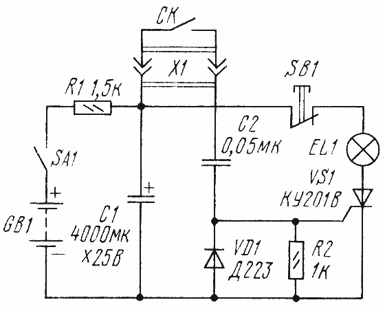
Encyclopedia of radio electronics and electrical engineering / Lighting When photographing photo reproductions and exhibits at close range, the energy of industrial "blitzes" often turns out to be unnecessarily high and, moreover, their use worries others. In such cases, it will be useful to illuminate the object being photographed with a flashlight with an incandescent lamp (Fig. 1), which is easy to make yourself without significant costs. Starting to shoot, the SA1 switch supplies power to the flash. Capacitor C1 is charged from battery GB1 to its voltage. Resistor R1 limits the charging current, which lasts about 12 s. When the camera shutter is released, the sync contact SK through the capacitor C2 supplies a voltage pulse to the control electrode of the trinistor VS1. The trinistor instantly closes the circuit of the incandescent lamp EL1, on which the capacitor C1 is discharged. The flash duration is approximately 1/50 sec., which makes handheld shooting possible. For this to be possible, the voltage across the charged capacitor must be about three times the operating voltage of the incandescent lamp. The reason for this is the thermal inertia of the lamp filament and the steeply falling characteristic of the discharge voltage of the capacitor. The initial peak of the discharge current is spent on heating the filament, after which a short-term bright glow appears in the overheating mode. To turn off the trinistor after operation and allow the capacitor to charge again for shooting the next frame, just press and immediately release the switch button SB1.
The relatively long charging of the capacitor with a small current makes it possible to use a very small power supply GB1 for the flash. So, with a lamp with a power of 15 ... 20 W from a filmoscope, designed for a voltage of 6 V, it can be made up of two or three Corundum batteries connected in series. Any trinistor of the KU201 series, any diode (except for that indicated on the diagram) of the D226 series can be used in a homemade flashlight. Capacitor C1 - K50-6, C2 - MBM, KLS, KM, resistors - MLT or MT with a power of at least 0,125 W. The connector for connecting to the sync contact can be made by yourself from a piece of single-core wire of a suitable diameter insulated with PVC and a thin-walled metal tube placed over the insulation. The whole device is placed in a ready-made or self-made case, equipped with a clip for mounting in the camera holder. A reflector - a reflector (for example, a large tablespoon) with a lamp can be recessed inside the flash body, parts and a power source are located around them on the board. The relative position of the parts does not play a role and is determined only by layout considerations. The lamp socket can be used from an old portable car light or you can build it yourself. A neatly assembled flash unit requires no adjustment. Since pulsing operation can shorten the life of the lamp, it is desirable to be able to easily replace the lamp. When shooting with this light, use a shutter speed of at least 1/30 s and, if possible, F-type slow sync. For cameras with a curtain shutter with X-type instant synchronization, some uneven illumination of the frame is possible when the lamp is installed above the optical axis of the camera. To correct this effect, it is better to install the flash on the bracket on the corresponding side of the device or shoot at a shutter speed of 1/10 s.
The described version of the flash is simple, but has a drawback - after each flash, you need to turn off the trinistor. This operation can be entrusted to automation (Fig. 2). The original version is supplemented by an electronic key on the transistor VT1, which is controlled by a single vibrator made on the transistors VT3, VT4, and the output stage on the transistor VT2. The multivibrator starts at the command of the sync contact SK simultaneously with the switching on of the trinistor VS1 and the lamp EL1. The transistor VT3 that closes at the same time opens VT2, which causes the VT1 key to interrupt the residual current (holding current) of the triggered trinistor. After about 0,5 s, the device will return to its original state and a new charge of the capacitor C1 will begin. The sensitivity of the single vibrator to triggering pulses can be adjusted by selecting the resistor R9, the reliability of closing the transistor VT1 - by selecting the resistor R4. Since the automation is powered, in order to avoid overloading the transistors, from a GB2 battery ("Korund"), it is necessary to change the batteries from time to time in order to use their capacity more evenly. In addition to those indicated in the diagram, transistors MP37B, MP38 can be used in the automation unit. Capacitors - oxide K50-6 (C1) and KLS (others), resistors - MLT or MT with a dissipation power of at least 0,125 W. Author: Yu.Prokoptsev, Moscow; Publication: cxem.net
Machine for thinning flowers in gardens
02.05.2024 Advanced Infrared Microscope
02.05.2024 Air trap for insects
01.05.2024
▪ A new record for the duration of thermonuclear fusion ▪ Determined the exact rate of expansion of the Universe ▪ Mini computer Shuttle XPC DA320
▪ section of the site Firmware. Article selection ▪ article The screw will not loosen. Tips for the home master ▪ article What do we breathe? Detailed answer ▪ article Violation of labor protection rules ▪ article Class A ultralinear amplifier. Encyclopedia of radio electronics and electrical engineering ▪ article The coin is rubbed into the neck. Focus Secret
Home page | Library | Articles | Website map | Site Reviews
www.diagram.com.ua |


 Leave your comment on this article: