|
|


 Arabic
 Bengali
 Chinese
 English
 French
 German
 Hebrew
 Hindi
Hindi Italian
 Japanese
 Korean
 Malay
Malay Polish
 Portuguese
 Spanish
 Turkish
 Ukrainian
 Vietnamese
|
ENCYCLOPEDIA OF RADIO ELECTRONICS AND ELECTRICAL ENGINEERING The two-channel switch - the regulator of lighting with remote control. Encyclopedia of radio electronics and electrical engineering
Encyclopedia of radio electronics and electrical engineering / Lighting This device is designed for both local and remote lighting control, using a standard electrical network ~ 220v 50 Hz. It contains two independent control channels, which in any combination can operate in one of two modes: 1. Switch mode. In this mode, when turned on, 100% of the mains voltage is immediately supplied to the load. It is used for energy saving lamps. 2. Regulator mode. In this mode, the load power can be smoothly adjusted. It is used for consumers such as incandescent lamps or halogen lamps (including those fed through an electronic transformer). Remote control of the switch is carried out by four buttons (two per channel) of any remote control that works with the widely used RC-5 command system. The remotes of this system are quite affordable and cheap. Advantages of this switch:
Functions performed by the switch:
Regulator control local government is carried out by two buttons located on the switch (one for each channel)
Remote control is carried out by the remote control directed towards the switch. To control the circuit breaker, four keys of the remote control are defined.
For each channel on the remote control, two keys are defined: turn on / increase power and turn off / reduce power in the load. The remote control button codes corresponding to these commands are stored in the EEPROM of the microcontroller. Thanks to this, in the learning mode (which is described in the manual), you can at any time change the set of remote control buttons that control the regulator. If at least one of the control channels is in the regulator mode, then it is possible to turn on / off both channels with one button pressed for more than 1 second. (more details in the instructions). When you press the control keys of the local control or on the remote control, a sound signal is emitted with a duration of ~0,2 seconds, which means that the command has been accepted. Circuit breaker device The regulator is built on an inexpensive and affordable microcontroller АТtiny2313-20PU. The schematic diagram of the device is shown below.
Power node serves to provide the microcontroller and the IR receiver with a supply voltage close to 5 V. The input voltage is rectified through the diode bridge VD1, quenched by the resistor R1, limited by the zener diode VD2, as a result of which a voltage of about 1V is formed on C2, C5. R2C3 elements are a filter in the photodetector power circuit. Synchronization node. R6R7R8C4 is the string required for zero detection. Resistors R6R7 dampen the input voltage, which is limited by the internal diodes of the PD2 output of the microcontroller. Capacitor C4 serves to suppress impulse noise. Each transition of the mains voltage through zero is processed 100 times per second. If the required and current power do not match, then the current one is corrected. This also makes it possible to implement a smooth switching on of the load in the regulator mode. Also, the double frequency of the mains is used to poll the local control buttons, the formation of time intervals for the glow of HL1 and HL2. Control and indication units. Buttons SB1 and SB2 are designed to control the first and second loads, respectively.
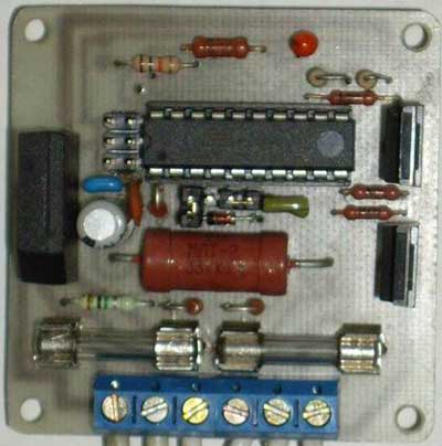
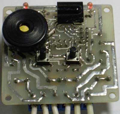
Switch node loads. From the output PB0 (PB1) of the microcontroller DD1, positive pulses through R9 (R10) open the transistors VT1 (VT2), through which the mains voltage is supplied to the corresponding load. Resistors R11 and R12 serve to prevent spontaneous opening of transistors at the time of power supply to the device, when the outputs PB0, PB1 are still in the third state and have not been configured by the MK program. The rectified mains voltage is supplied to the load, which is acceptable for the lamps used. Selection of operating mode is carried out by jumpers S1 and S2 for the first and second channels, respectively. If there is no jumper, then the channel is in the regulator mode, and if installed, then the switch. Regulator design The regulator is assembled on a single-sided printed circuit board made of foil fiberglass, the drawing and location of the parts of which are in the attached files. On the side of the printed conductors, elements HL1, HL2, B1, SB1, SB2, HA1 are installed. The remaining elements are installed on the opposite side. The board is fastened with D2.5mm screws at the corners. The power transistors are specially placed on the edge of the board so that heatsinks can be easily attached to them if the load being used draws more than 100 watts.
Used parts and possible replacements To control the regulator, you can use any remote control that works according to the RC-5 protocol. The DD1 microcontroller can be replaced with an ATtiny2313-20PI or ATtiny2313V-20PU(PI), and the B1 photodetector can be replaced with a similar one, designed for a carrier frequency of 36 kHz, for example, TSOP4836, TSOP1836SS3V, SFH506-36, SFH5110-36, TFMS5360, but note that the location the outputs of photodetectors of different types may differ. Transistors VT1, VT2 can be IRF840A or domestic analogues of KP840, KP707, but it should be noted that for all these transistors, unlike 2SK2545, the surface for attaching the heat sink is not isolated from the drain, so they can only be mounted on a common radiator through insulating gaskets. We will replace the VD2 zener diode with BZX79C5V1, BZX55C5V1, 1N4733A, or you can choose domestic KS156A, G KS456A, G so that the stabilization voltage does not exceed 5,5V. Instead of HL1 HL2 LEDs, you can use HB3B-446ARA, ARL-3214URC-10cd or similar super-bright ones. The diode bridge VD1 must be designed for a current not less than the total current consumption by both loads and for a reverse voltage of at least 400V. HA1 - any two-pin piezoelectric tweeter. The fuse holders used are brand FH-100. Fuses protect power elements from overload and short circuit. Their rating should be 2 ..... 2,5 times higher than the current consumption of the load used. Assembly and adjustment of the regulator At the beginning, all elements except DD1, B1, C4 are soldered onto the board. Turning on the regulator in the network, measure the DC voltage on C1 and then on C3. In both cases, it should be around 5V. Then the tracks on the board are connected in series with a jumper, going to the 20th and 5th, 20th and 4th pins of DD1, while HL1 and HL2 should light up, respectively. Now we need to check the operation of the control channels. To do this, turn off the power, connect as loads, for example, incandescent lamps up to 100W, turn on the power supply to the left terminals R9, R10 according to the diagram from the + 5V power supply (for example, by closing the tracks on the board with a jumper, going to 20 and 12, 20 and 13 terminals of DD1. In this case, the lamps of the first and second channels should light up, respectively. If everything went well, then disconnect the regulator from the network, solder DD1 (although it is better to put a socket for it) and B1, C4 and connect the programmer to the XP2 connector (standard a six-pin connector for in-circuit programming of the AVR). (flash EEPROM is also a must!!!) The FUSE bits of the DD1 microcontroller must be programmed as follows: • CKSEL3...0 = 0100 - clocking from the internal RC oscillator 8 MHz;
For the regulator mode, as mentioned above, you can set individually for each channel the lower power control threshold. To do this, you need to write the value for the first and second channels, respectively, into the EEPROM cells at $01 and $02. In this device, in the range from 0% to 100%, there are 127 steps of regulation. Thus, to set the lower threshold at a level, for example, 25%, you need to multiply this value by 1,27 (25 * 1,27 = 32) and write down the value 32 ($20) to the corresponding cell in the EEPROM. Initially, zeros are written in both cells. The instruction manual is in the attached files. The switch has a remote control compatibility check mode. To do this, you need to set both channels to the regulation mode, turn them on, set the minimum power level on them, and turn them off. Then press any button on the remote control and if it works according to the RC-5 system, an audible signal will sound for 1 second. The permissible total power of the switched load in each channel without a radiator is 100 W. With a larger one, it is necessary to install transistors on a heat sink of the appropriate area. The regulator is designed to control only those types of loads that are indicated at the beginning of the article. They can be powered by rectified mains voltage. Do not connect other devices, such as fluorescent lamps or electric motors, to it. This may damage the regulator. Attention! When assembling and adjusting the regulator, remember that all its elements are under mains voltage and touching them can lead to electric shock. Download project files in one archive : diagram, demo firmware, printed circuit board drawings, instruction manual Author: Alexey Batalov, alexperm72@yandex.ru, ICQ#: 477022759; Publication: mcuprojects.narod.ru/projects.html
Machine for thinning flowers in gardens
02.05.2024 Advanced Infrared Microscope
02.05.2024 Air trap for insects
01.05.2024
▪ Fujitsu Primergy servers based on Intel Xeon E5 v4 processors ▪ Remote shutdown of car engines
▪ site section Tone and volume controls. Article selection ▪ article Gentle, quiet word to remember (remember). Popular expression ▪ article Does the turtle have a voice? Detailed answer ▪ article Construction electrician. Standard instruction on labor protection ▪ Velofar's article on LEDs. Encyclopedia of radio electronics and electrical engineering
Home page | Library | Articles | Website map | Site Reviews
www.diagram.com.ua |


 Leave your comment on this article: