|
|


 Arabic
 Bengali
 Chinese
 English
 French
 German
 Hebrew
 Hindi
Hindi Italian
 Japanese
 Korean
 Malay
Malay Polish
 Portuguese
 Spanish
 Turkish
 Ukrainian
 Vietnamese
|
ENCYCLOPEDIA OF RADIO ELECTRONICS AND ELECTRICAL ENGINEERING Chips TC9148-9150 for remote control of household equipment. Encyclopedia of radio electronics and electrical engineering
Encyclopedia of radio electronics and electrical engineering / Clocks, timers, relays, load switches With the help of the following writings (a lot of writings, I warn you), Cat (Meow!) and I will try to clearly explain how to make a remote control of an audio-video complex in one evening, if you have one. There is a corporation called TOSHIBA - heard somewhere, right? And this corporation has a division of semiconductors and electronic components. And this very department fussed and released three microcircuits - TC9148P, TC9149P, TC9150P. In fairness, it must be said that this fuss was quite a long time ago - about 15 years ago, however, the microcircuits turned out to be so successful that they are still used with a bang wherever they hit. TC9148P - encoder-transmitter SDU.
This chip, two transistors and a dozen buttons - all you need to build a full-fledged transmitter for the SDU. The chip allows you to send 10 different commands with the possibility of expanding to 18 commands. The supply voltage can vary in the range of 2,2-5,5 volts. Current consumption in rest mode (no button pressed) - 10 uA. Transmission frequency - 38kHz. Let's run through the findings: 1 Earth
When you press the button, the microcircuit generates the corresponding code package 12 bits long, the built-in generator produces a carrier at a frequency of 38 kHz, and all this vinaigrette is output. Next - two microcircuits at once - TC9149P and TC9150P - SDU decoder receivers.
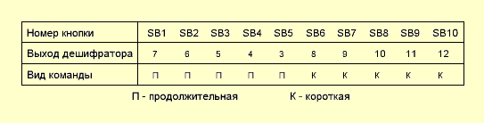
Well, it is clear that if there is a transmitter that also encrypts something, then somewhere there must be a receiver that can decrypt something. These microcircuits are engaged in the fact that they decode the transmitter's code packets and, in accordance with the message, turn on / off their outputs. These two differ only in one thing - the amount of output. The TC9149P has 10 for 10 commands, while the TC9150P has 18 for 18 commands. Now let's talk a little about the commands themselves. The figure shows that the outputs marked as Outputsfor some reason they are labeled differently. And here's the thing. All commands transmitted by the transmitter are divided into three groups: short, lengthy и cyclical. The buttons of the transmitter and its inputs, as well as the outputs of the receiver, are rigidly tied to each group. When executing short commands, the decoder outputs marked as SP (Short Pulse) and they are performed as follows:
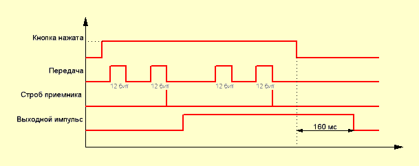
When you press the transmitter button, two identical code parcels of 12 bits long are formed. The decoder receives these messages, calculates the checksum, and if everything is fine, issues a strobe pulse, upon arrival of which a logical unit appears at the corresponding output. The output stays high for approximately 107 ms. after which the output is again set to its original state - a logical zero. Moreover, it does not depend on whether the button on the transmitter is released or not. To repeat the command, press the button on the transmitter again. Such commands can be used, for example, to turn on / off the power of the equipment, MUTE or ST-BY mode. When executing long commands, the outputs of the decoder are activated, indicated HP (Hold Pulse) and work like this:
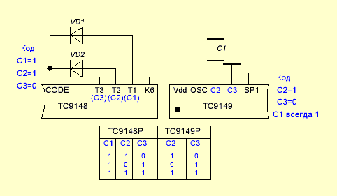
After pressing the button of the transmitter, it starts to issue sequences of paired 12-bit pulses. After processing the first pair by the decoder and issuing a strobe pulse, the output is transferred to a high level state and this state continues as long as the transmitter button is pressed. After the button is released from pressure, the high level state remains at the output for approximately 160 ms, after which the output goes to its initial state - logic zero. Commands of this type can be used when adjusting the volume, tone, or something else like that. There is a third option - cyclic commands - CP (Cyclic Pulse). They are available only when the TC9150P chip is used as a decoder. Their essence lies in the fact that the output state changes to the opposite each time the transmitter button is pressed. Once pressed - the output turned on, the second time - turned off. Now let's see what the output does CODE on the transmitter chip and finally move on to the slides. In a sense, to specific switching schemes. Be patient - there's a lot left. Anything can happen in life, including the fact that you need two or three transmitters to control two or three devices. And how to do this if our transmitter and receiver are exactly the same? For such a case, smart heads from the above-mentioned office came up with the idea of adding the so-called identification code to the transmitter's code package so that the receiver could understand whether it should process the incoming signal or, well, its nafik - the signal came from someone else's transmitter. To do this, the transmitter has an output CODE, and in the decoders the conclusions C(x). Let's see how it works. Let's take a pair of TC9148-TC9149 first.
So, in the transmitter, the code is formed using diodes connected between the CODE pin and the T1-T3 pins. In the decoder, a similar code is set by connecting a capacitor between the common wire and terminals C2 and C3. The table shows code options. Note that in TC9149 code C1 is always 1, while C2 and C3 are set as described above. Now let's take the TC9150. There is a completely similar situation, except that C3 is already set permanently and equals 1, and C1 and C2 are set.
Thus, we can use three transmitters and three receivers in the same room, simply by setting different identification codes on them. By the way, it is worth noting that code 00 is prohibited by the manufacturer and cannot be used. Ugh! Exhaled. Smoked. If you still don’t understand a damn thing - don’t worry - now everything will become clear with examples (probably). Let's start with the transmitter.
As mentioned above - external components - a minimum. Selected 10-button option - draw less. Since the option is 10-button, then there are 10 commands, and therefore our decoder for today is TC9149P.
According to this scheme, the receiver performs only two commands for us - power on / off and MUTE on / off. Both are implemented using short commands. By the way, here's another thing - they forgot about the correspondence of the transmitter buttons and receiver outputs. Now let's fix it - look at the plate:
As you can see, there are no cyclic commands here - for this you need to use another decoder - TC9150P. Well, under it, you can also get hold of eight buttons on the transmitter. Just what you will do with all this - I have no idea. So share your thoughts on this and don't forget to ask questions. Publication: radiokot.ru
Machine for thinning flowers in gardens
02.05.2024 Advanced Infrared Microscope
02.05.2024 Air trap for insects
01.05.2024
▪ China begins research into 5G communications
▪ section of the site Electrician's Handbook. Article selection ▪ article Vegetable cutter from the washing machine. Drawing, description ▪ article What is the number of the Beast? Detailed answer ▪ article Deputy Director for Retail. Job description ▪ article Iridescent coin. Focus secret
Home page | Library | Articles | Website map | Site Reviews
www.diagram.com.ua |


 Leave your comment on this article: