|
|


 Arabic
 Bengali
 Chinese
 English
 French
 German
 Hebrew
 Hindi
Hindi Italian
 Japanese
 Korean
 Malay
Malay Polish
 Portuguese
 Spanish
 Turkish
 Ukrainian
 Vietnamese
|
ENCYCLOPEDIA OF RADIO ELECTRONICS AND ELECTRICAL ENGINEERING Musical calls with automatic selection of melodies. Encyclopedia of radio electronics and electrical engineering
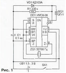
Encyclopedia of radio electronics and electrical engineering / Calls and audio simulators In order to change the melody played by the UMS, it is necessary during its sounding or within a few tenths of a second after the end to apply a high logic level pulse to the "Melody Selection" (VM) input of the synthesizer microcircuit. In the latter case, the next melody starts playing regardless of the logic level at the "Start" (S) input On fig. 1 shows a diagram of the simplest call, which automatically enumerates all melodies available in the UMS memory.
A logic 13 is constantly applied to pin 1 of the DD1 chip, so after turning on the power, the first of the melodies starts playing. Short low-level pulses at the inverse output DD1 (pin 14) through the diode VD1 discharge the capacitor C1. Although in the intervals between pulses this capacitor is slightly charged through the resistor R1, while the melody is playing, the voltage on it does not have time to reach the threshold of the VM input. This will happen only after the end of the melody and the cessation of the pulses, when a constant voltage is established at pin 14 DD1, close to the supply voltage. As a result, the next melody will be played, and the pulses that appear again at pin 14 DD1 will discharge the capacitor C1. Conflicting requirements are imposed on the time constant of the R1C1 circuit. On the one hand, it must be large enough so that the capacitor does not have time to charge about the intervals between pulses, on the other hand, at the end of the melody, it must have time to charge before it starts to be played again. The situation is aggravated by that. that there are melodies consisting of two or more parts, separated by rather long pauses. Such a melody may change before it sounds completely. The call is assembled by surface mounting directly on the pins of the DD1 chip. which is best to use UMS8-08 or UMS7-08. UMS7-01 is also suitable. Diode VD1 - any low-power silicon, for example, series KD102. KD103. KD521. KD522. Resistor R1 - MLT-0.125. capacitor C1 - KM-6. Establishment consists in the selection of the resistor R1. If the melody changes too soon, it is necessary to increase its resistance. If it "loops", the resistance should be reduced. By embedding a bell in a watch that has its own generator operating at a frequency of 32768 Hz. the quartz resonator ZQ1 can be omitted. Pin 3 of the DD1 chip in this case is connected to pin 5. and a generator signal is sent to pin 7. You can connect output 7 directly to one of the outputs of the quartz resonator of the clock, which one is determined experimentally. A more complex call, the scheme of which is shown in Fig. 2, is guaranteed to reproduce all melodies recorded in the synthesizer's memory in full. In addition to UMS DD4. it has nodes for generating control pulses (DDI.2, DD2, DD3.3, DD1.6). output disable (DD3.1, DD3.2, DD3.4) and clock generator (DD1.1, DD1.3-DD1.5).
After the supply voltage is applied, the direct output of the DD4 microcircuit (pin 1) is set to a low level and the capacitor C1 is charged through the resistor R1 As soon as the voltage across the capacitor falls below the switching threshold of the DD1.2 element. the low logic level at the output of the latter will be replaced by a high one. This will transfer the counter DD2 to its initial state and set the trigger from the logic elements DD3.1 and DD3.2 to a state that prohibits the passage through the element DD3.4 of the signal from pin 14 of the DD4 chip to the base of the transistor VT1 In the initial state of the counter DD2, a high logic level with its output O (pin 3) through the elements DD3.3 and DD1.6 goes to pin 13 of the DD4 chip and the generation of the melody begins. But the very first high-level pulse at pin 1 of the UMS through the diode VD1 will discharge the capacitor C1. and a low logic level at the output of the element DD1.2 will allow the counter DD2. With each pulse of the clock generator (elements DD1.1. DD1.4, DDI.5), high-level pulses alternately appear at the outputs of the counter. Its outputs 1 and 2 are connected respectively to the "Melody Select" (BM) and "Stop" (R) inputs of the DD4 microcircuit, therefore, after the first pulse of the clock generator, the melody will change, but it will not sound, since the DD4 output signals do not pass through element DD3.4. The second pulse will stop the synthesizer. The third pulse of the generator will set a high logic level at pin 7 of the counter DD2. Elements DD3.3 and DD1.6 will transfer it to pin 13 of the DD4 chip and playback of the next melody will begin. Simultaneously switch trigger DD3.1. DD3.2. allowing the passage of the sound signal through the element DD3.4. The next clock pulse will set a high logic level at pin 10 of the counter DD2, which will go to its pin 13 and prohibit further counting. After the end of the melody, the capacitor C1 will charge again and the described cycle will repeat. Call details can be mounted on the board, the sketch of the printed conductors and the location of the elements on which are shown in fig. 3.
A panel should be provided for the DD4 chip, which will allow you to quickly change the set of melodies if necessary. In addition to UMS8-08 indicated on the diagram, UMS4-7 is suitable as DD01. The UMS7-03 and UMS7-05 microcircuits are unsuitable in this case, since they stop playing the melody shortly after the enable signal is removed at pin 13. Instead of the K561IE8 microcircuit, you can install the K561IE9, taking into account the differences in the assignment of their conclusions. Transistor VT1 can be any of the KT312, KT315 or KTZ102 series. Diode VD1 - any low-power silicon. Resistors MLT-0,125. Capacitors C1 and C2 (oxide) - K50-35 or K50-40, C3 - KM-5. KM-6. A 3 V power supply is connected to pads B (plus) and C (minus). Galvanic cell GB1 size A286 (AAA) is not needed in this case. It is set if the device works in conjunction with an electronic clock powered by a voltage of 1.5 V from one galvanic cell. Contact pad A is connected to the positive pole of the latter, and B to the negative pole. Moreover, the alarm switch must break one of these circuits. In total, the two elements will give the required 3 V. Site G is connected to the output of the clock's quartz oscillator. If necessary (for example, if the generator frequency in hours differs from 32768 Hz), you can turn on the resonator at the desired frequency between pins 7 and 8 of the DD4 chip. as it was shown in fig. 1. In this case, its pin 3 should not be connected to a power source, but to a common wire (pin 2). The output signal of the call is taken from the emitter (contact pad E) or from the collector (contact pad D) of the transistor VT1. In the first case, its collector is connected to the power source (site B) directly, in the second - through a resistor or other load. On fig. 4 shows how to connect a bell to a common M5188-X electromechanical watch. Having removed the cover from them, they carefully solder from the printed circuit board, on which all the electronic components of the clock are located, the conclusions of the coil L1. remove it from the case, and then the board. In the places marked in the figure with crosses, the printed conductors are cut. The contact pads of the battery and the SA1 alarm switch are connected by a jumper from an insulated wire.
The VT1 transistor present in the watch, which can be replaced by the domestic KT503 series, together with the bell VT1 form a composite transistor that controls the BF1 sound emitter. A supply voltage of 3 V will be supplied to this stage from contact pad B. In parallel with the emitter, a VD1 diode is connected - any of the KD102, KD103, KD521, KD522 series. Capacitor C1 with a capacity of 1000 pF, which is present in some copies of the clock, is removed. The clock and bell boards are connected by six wires. Then the clock board is installed in place and its connection to the L1 coil is restored. A properly assembled call does not require adjustment. When checking it, it should be taken into account that the sound signal will appear 5 ... 7 s after the supply voltage is applied. The duration of the pause between melodies can be changed by selecting the resistor R1. Author: A. Shitov, Ivanovo
Artificial leather for touch emulation
15.04.2024 Petgugu Global cat litter
15.04.2024 The attractiveness of caring men
14.04.2024
▪ Navigator in the windshield of a car ▪ Antimatter in the framework of quantum theory: both particle and wave
▪ section of the site Stories from the life of radio amateurs. Selection of articles ▪ article Iron and blood. Popular expression ▪ article Who made the first glasses? Detailed answer ▪ article Signs of a change in inclement weather to clear. Travel Tips ▪ article Restoring readability CD. Encyclopedia of radio electronics and electrical engineering ▪ article Input circuits and RF receiver. Encyclopedia of radio electronics and electrical engineering
Home page | Library | Articles | Website map | Site Reviews
www.diagram.com.ua |


 Leave your comment on this article: