|
|


 Arabic
 Bengali
 Chinese
 English
 French
 German
 Hebrew
 Hindi
Hindi Italian
 Japanese
 Korean
 Malay
Malay Polish
 Portuguese
 Spanish
 Turkish
 Ukrainian
 Vietnamese
|
ENCYCLOPEDIA OF RADIO ELECTRONICS AND ELECTRICAL ENGINEERING Incubator kinematics control unit. Encyclopedia of radio electronics and electrical engineering
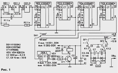
Encyclopedia of radio electronics and electrical engineering / Power regulators, thermometers, heat stabilizers This electronic unit is designed to automatically control the rotation of trays with eggs from the initial position at an angle of 90 degrees with an interval of one hour. One of the disadvantages of a similar device described in "Radio" (see the article by O. Glagolev "Electronic automation of a small-sized incubator" in No. 3, 1997, pp. 45, 46) is the difficulty of adjusting the switching unit of limit switches, which are triggered for calculation of the inertia of the electric motor. In practice, this is very difficult to achieve, especially at a low rotational speed of the actuator. The block described below is free from this shortcoming. The element base and ease of manufacture are available even for not very qualified radio amateurs. The control unit (see diagram in Fig. 1) contains a second pulse generator based on DD1.1-DD1.3 elements, a frequency divider on DD2-DD5 microcircuits with a total division factor of 3600, a D-trigger (DD6.1), an electronic switch ( transistor VT1), actuator (relay K1, motor M1, limit switches SF1 and SF2). The device does not have a circuit for pre-setting the counters to the zero state, since the moment the actuator is turned on in the first cycle does not matter, yet the subsequent ones are repeated at intervals of 60 min + 15 s.
Second pulses from the output of the element DD1.3 are fed to the frequency divider. Depending on the position of the SA1 switch, minute or hour pulses are fed to the input of the D-trigger (element DD6.1) and switch it. The high-level voltage that occurs at the direct output of the trigger opens the transistor VT1, which turns on relay K1 and holds it in this state until the next pulse. Relay contacts K1.1 through one of the limit switches, which is closed at this moment (in the diagram - SF2), connect the electric motor to the power circuit. When the actuator reaches the limit switch SF2, the latter opens, turning off the power supply circuit of the electric motor. The limit switch SF1, which closes at the beginning of the movement of the actuator, prepares the power supply circuit of the electric motor for a new cycle. In the next cycle, the output of the D-flip-flop is low-level voltage: the transistor closes, the relay is de-energized, contacts K1.1 and K1.2 return to their original state and reconnect the motor to the power circuit, but in the opposite polarity relative to the previous cycle. The "1 min" mode is necessary to set the generator frequency equal to 1 Hz with a tuning resistor R1, and during operation - to install the trays in a horizontal position. The motor is switched off in this case by the switch SA2. Capacitors C7 and C8 suppress interference in the power supply circuit of a running engine. All parts of the unit, with the exception of diodes VD3, VD4, capacitors C7, C8, limit switches and switches SA1, SA2, are mounted on a printed circuit board made of foil fiberglass with dimensions of 65x80 mm (Fig. 2). The board has holes "a" and "b" for mounting capacitor C2.
Relays RES-48 (passport RS4.590.204 or RS4.590.216), RES-9 (RS4.529.02903, RS4.529.029-10, RS4.529.029-12, RS4.529.029-15, RS4.529.029-16 or RS4.529.029-19) with an operating voltage of 5 V. It is permissible to use a relay for an operating voltage of 12 V. In this case, its winding is powered from the same source as the electric motor. Capacitors C1, C2 - K50-35, C7, C8 - K50-6, the rest are ceramic. Trimmer resistor R1 - SP5-2. Limit switches SF1 and SF2 - MP1-1 microswitches. Switches SA1 and SA2 - toggle switches MT1. Electric motor - DPM-25N3-0,1 A. It is possible to use an AC motor for a voltage of 220 V with a gearbox, for example, DSM2U42-P-220 50 Hz with a power of 4 V∙A. In this case, the device should replace the relay with a triac and use both outputs of the trigger DD6.1 (Fig. 3). The kinematic diagram of the actuator for this option is shown in fig. 4. Driving disc A is rigidly connected to the motor gearbox shaft and rotates in one direction only. Rotation of disk A by 180 degrees corresponds to rotation of driven disk B by 90 degrees. Further rotation of the master disk causes the slave to rotate in the opposite direction. The given dimensions are determined experimentally. With any type of engine, it is necessary that the time for turning the actuator by 90 degrees (i.e., the time interval between switching the limit switches) does not exceed 1 minute. To power the unit, any source for two voltages is suitable: a stabilized 5 V and an unstabilized 12 V. When replacing a relay with a RES-9, you need to partially modify the pattern of the printed circuit board. Author: A. Grigoriev, Balashov, Saratov region
Machine for thinning flowers in gardens
02.05.2024 Advanced Infrared Microscope
02.05.2024 Air trap for insects
01.05.2024
▪ The inscription on the diamond ▪ Detection of ultraweak radio waves using a laser ▪ 1/4" 8 MP OmniVision OV8856 and OV88565 image sensors ▪ Electric scooter NIU Gova C0
▪ section of the site Note to the student. Article selection ▪ article Enemy of the people. Popular expression ▪ Article Medical Specialist. Job description ▪ article Voltmeter with a linear scale. Encyclopedia of radio electronics and electrical engineering ▪ article Sugar from sawdust. Chemical experience
Home page | Library | Articles | Website map | Site Reviews
www.diagram.com.ua |


 Leave your comment on this article: