|
|


 Arabic
 Bengali
 Chinese
 English
 French
 German
 Hebrew
 Hindi
Hindi Italian
 Japanese
 Korean
 Malay
Malay Polish
 Portuguese
 Spanish
 Turkish
 Ukrainian
 Vietnamese
|
ENCYCLOPEDIA OF RADIO ELECTRONICS AND ELECTRICAL ENGINEERING Digital Thermometer. Encyclopedia of radio electronics and electrical engineering
Encyclopedia of radio electronics and electrical engineering / Power regulators, thermometers, heat stabilizers Using this device, you can measure the temperature in vegetable and granaries, in the room and on the street, and when placing sensors in the hive, you can receive additional information about the state of the bee colony during the wintering period, for which, in fact, the thermometer was developed. Limits of measurement of the thermometer - +50...-50 °C. Measurement accuracy - 0,3°С (depends on the class of microammeter used). Diode D223 is used as a sensor, which is connected by a shielded wire (through a tape connector installed on the rear wall of the hive) to an electronic thermometer. Consider a simplified device diagram (Fig. 1).
The temperature sensor (i.e., temperature-sensitive element) is a silicon diode. At room temperature, a current of 1 ... 2 mA passes through an open diode, the voltage drop is usually 600 mV. As the air temperature increases, the voltage across the diode decreases linearly by 2,2 mV for every degree Celsius. This dependence is clearly preserved in the range from 0 to 100°C. As a temperature indicator, a sensitive microammeter with zero in the middle of the scale is used, connected to the sensor diodes through a bridge circuit. The bridge is considered balanced if the voltage at points A and B is the same. When the diodes D1 and D2, which are temperature sensors, are heated, the voltage drop across them decreases. In this case, the balance of the bridge is disturbed and the digital value of the unbalance is shown by the pointer of the PA1 device. Adjustment and calibration Having previously turned off the RA1 device, turn on the power and check against the "-" voltage at points A and B. They must be equal to each other and be within 1 ... 1,2 V. If the voltage at point B is equal to the supply voltage (4,5, XNUMX V), then the diodes are connected incorrectly, their polarity must be reversed. If the voltage difference at points A and B is small, it is equalized with a tuning resistor R4. Having achieved a satisfactory result, set the minimum resistance of the resistor R3, turn on the pointer device in the circuit and supply power. Then, with resistor R4, the arrow of the device is set to 20 ° C (or other room temperature), controlling the air temperature with a mercury thermometer. Next, clamp the measuring diodes with your fingers and look at the arrow. It should smoothly deviate to the right and stop at about a division of 30 ° C. If the arrow moves to the left, it is necessary to reverse the power supply polarity of the device. The thermometer is calibrated at two points - at the beginning and at the end of the scale. To calibrate the starting point, a vessel with melting ice taken from the freezer of the refrigerator is used. The temperature of melting ice is 0°C. The adjustment is carried out with a resistor R5. Then the temperature sensor (diodes) is lowered into water, the temperature of which is 50°C. In this case, the adjustment is made by the resistor R3. For reliability, the calibration of both points of the scale is done 3 times, controlling the temperature of the points 0°C and 50°C with a mercury thermometer. A diagram of a more accurate and convenient thermometer is shown in Fig. 2.
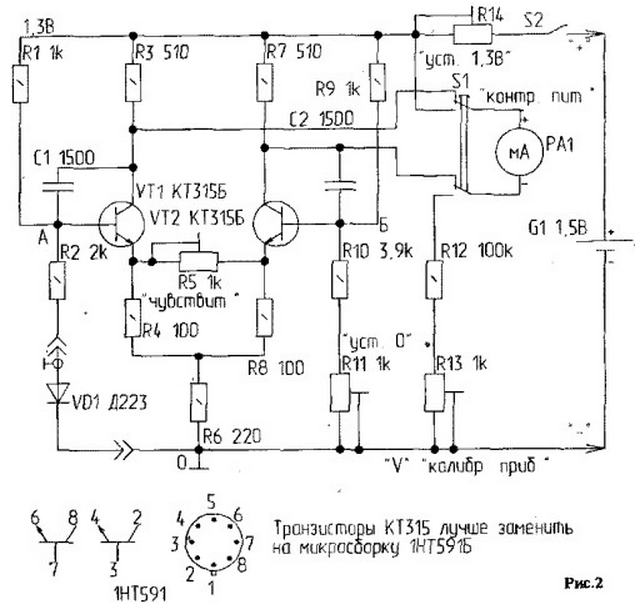
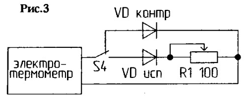
It is powered by a single 1,5 V galvanic cell, which is important, and is designed to measure the temperature at various points in the hive, which provides information about the state of the bee colony. Diode D-223 or - if necessary - a group of diodes is used as sensors. They can be combined on a flat fiberglass bus or grouped on a wire that is a common wire, as well as on separate pairs of wires to obtain information at points spaced at the required distance. It should be borne in mind that the resistance of the AO arm (resistor R2 + resistance of the diode or diodes D-223) must be equal to the resistance of the OB arm (resistor R10 + trimmer resistance R11). If one diode is used as a sensor D, the resistance of the resistor R10 is approximately 3.9 kΩ, if three diodes D223 are approximately 5,9 kΩ. This is due to the fact that the resistance of the D223 diode is 720 ... 725 ohms at a current through the diode equal to Ipr-0,4 mA and 16 ohms at a current of 50 mA. The thermometer is a balanced bridge, the diagonal of which includes a two-phase amplifier with a symmetrical output to the indicator. The arm of the AO bridge includes a silicon junction resistance, which is a temperature sensor. The bridge is made up of resistors R1, R2, R9, R10, trimmer R11 and silicon junction resistance of diode D1. The paraphase amplifier is assembled on transistors VT1 and VT2 of the KTZ15, KT342 type. It is desirable that the triodes be selected according to the gain. The load of the collector circuits are the resistances R3 and R7. Resistor R6 is a common emitter coupling resistor, and R4, R8 and R5 are cascade sensitivity adjustment elements. Shunt trimmer R5 determines the sensitivity of the device. The bases of the transistors are blocked by capacitors C1 and C2 included in the diagonal of the bridge. A microammeter with measurement limits of 50-0-50 μA is connected between the collectors of the triodes. Power is supplied from a 1,5 V element through a quenching variable resistor R14. Setting 1. Set the power supply to 1,3V using R14. 2. Close the bases (the deviation of the arrow from "0" is allowed by +1 division). If the arrow deviates by more than one division, resistors R3 and R7 should be selected. 3. Open bases VT1 and VT2. Immerse the sensor in water with snow or ice and set "0" with the trimmer R11 - The water temperature is controlled by a mercury thermometer. 4. Immerse the sensor in water at a temperature of 50°C. If the microammeter readings do not correspond to 50, the arrow should be set to this mark using resistor R5. 5. Lower the sensor into an environment with zero temperature and check if the pointer is set to zero. If not, adjust R11. 6. Check the PA1 readings again by immersing the sensor in water at a temperature of 50°C. To control the power supply of 1,3 V, connect a microammeter to the control circuit by pressing the SI - P2K button, then set the desired voltage with a trimming resistor R14. The voltmeter is calibrated using R13 within 0 ... 5 V when the thermometer is disconnected from the power supply and comparing its readings with a reference voltmeter at this scale (0 .. .5 V) resistance R12 \u100d 5k, because R=U/I=0,05/100=XNUMX k. Diodes have a large spread in resistance, so they need to be selected. First select the one whose resistance is greatest at room temperature. It is selected using a digital voltmeter-multimeter of type B7-20 or similar, since it is difficult to find a diode with the highest resistance with a tester, and a voltmeter allows you to measure the voltage drop across the diode at a given current. This sensor will be the control. Relative to it, additional resistances (makeweights) are selected for other diodes (Fig. 3).
Wires are soldered to the terminals of the diodes so that the diodes can be lowered into water, the temperature of which is constantly monitored by a mercury thermometer. With the help of switch S4, the exemplary control diode (by which the electrothermometer was tuned) and the subject are connected in turn to the electrothermometer. Trimmer resistor R1 achieve the same readings of the microammeter RA1. Then, having measured the resistance of the trimmer R1 with a tester or multimeter with the diodes turned off, the value of the resistance of the appendage is determined - a constant resistance, which is soldered in series with the diode under test. In the same way, makeweights are selected for other sensor diodes. Selected diodes (with appendages) are installed at the right points in the hives and connected via a connector to the thermometer. The screen of the wire is connected to the negative bus, the central core is connected to R2 of the thermometer. The thermometer can also be used in other branches of agriculture. Author: A.Kukharenko, Grodno, Belarus
Machine for thinning flowers in gardens
02.05.2024 Advanced Infrared Microscope
02.05.2024 Air trap for insects
01.05.2024
▪ Glass that generates solar energy ▪ Photo recognition determines your exact location ▪ Satellites for registering gravitational waves
▪ section of the site History of technology, technology, objects around us. Article selection ▪ article Wolf in sheep's clothing. Popular expression ▪ article What is light? Detailed answer ▪ article Operation of electric hoists. Standard instruction on labor protection ▪ article Mixer for symmetrical lines. Encyclopedia of radio electronics and electrical engineering
Home page | Library | Articles | Website map | Site Reviews
www.diagram.com.ua |


 Leave your comment on this article: