|
|


 Arabic
 Bengali
 Chinese
 English
 French
 German
 Hebrew
 Hindi
Hindi Italian
 Japanese
 Korean
 Malay
Malay Polish
 Portuguese
 Spanish
 Turkish
 Ukrainian
 Vietnamese
|
ENCYCLOPEDIA OF RADIO ELECTRONICS AND ELECTRICAL ENGINEERING Shimmering flower. Encyclopedia of radio electronics and electrical engineering
Encyclopedia of radio electronics and electrical engineering / Lighting A pleasant surprise on the Christmas tree, no doubt, will be a two-color shimmering flower. This device uses seven two-color LED diodes, which are arranged on a printed circuit board in the form of flower petals. At the same time, they alternately glow either green or red. The LED located in the center of the flower is also bicolor, but while the rest of the LED diodes light up, for example, in green, it glows in red, and vice versa. This simple device is designed as a separate module that can be placed on a Christmas tree as a decoration or built into any toy or souvenir. The multi-colored flickering flower module is a simple switch in which the supply voltage is alternately applied to two groups of LEDs. The schematic diagram of the device is shown in the figure.
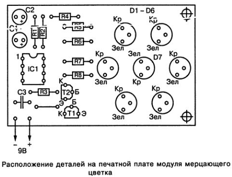
The proposed device, which is made on just one microcircuit and two transistors, can be conditionally divided into three functional blocks: a master oscillator, a control unit and an indication circuit. The master oscillator that generates control pulses is made on the IC1 microcircuit, which is connected according to the unstable multivibrator circuit. In this case, the switching frequency of the multivibrator is determined by the value of the resistance of the resistor R1 and the value of the capacitance of the capacitor C1. Switching pulses from the master oscillator output (output IC1/3) are applied to the bases of transistors T1 and T2, which provide direct voltage supply to the corresponding groups of LEDs. When a continuous sequence of positive and negative control pulses is formed at the output of IC1 (pin IC1 / 3), transistors T1 and T2 will alternately turn on. So, when transistor T1 is unlocked by a positive pulse through its open collector-emitter junction, the anodes of the corresponding group of double LEDs D1-D7 will be connected through resistors R5 and R7 to the plus of the power source, which will lead to the glow of these diodes one of the colors. At the end of the control pulse, transistor T1 will close again, and the LEDs will go out. When the transistor T2 is unlocked by a negative pulse through its open collector-emitter junction to the plus of the power source through resistors R6 and R8, the anodes of the second group of double LEDs D1-D6 will be connected. As a result, these LEDs will begin to glow in a different color. At the end of the pulse, transistor T2 will close again, and the LEDs will go out. The arrival of a sequence of control pulses from the master oscillator (IC1) to the bases of the transistors will ensure that the diodes alternately glow until the power is turned off. The two-color LED D7 located in the center of the flower is turned on in such a way that when the other diodes light up green, it glows red, and vice versa. All parts of the shimmering flower module are placed on a 68x42 mm printed circuit board. The printed circuit board is shown in the figure.
The location of the parts on the printed circuit board of the device is shown in the figure.
Instead of two-color LEDs, you can use any single-color LED diodes. In this case, one bicolor diode is simply replaced by two ordinary LEDs of different colors by connecting their cathodes. However, in this case, it is necessary to make appropriate changes to the pattern of the printed circuit board by drilling additional holes. The pnp transistor VS557V (T2) indicated in the diagram can be replaced, for example, with a domestic transistor of the KT668V type. Instead of the VS547V (T1) npn transistor, you can install a domestic transistor of the KT3102BM type. The installation of elements on the printed circuit board should be carried out in the usual manner, that is, first you need to solder the jumper and the socket of the microcircuit, then the resistors and capacitor C3, transistors and capacitors C1 and C2. After that, you can install LEDs on the printed circuit board of the module. During the installation of elements, special attention must be paid to the correct arrangement of the terminals of transistors, electrolytic capacitors and LEDs. At the same time, for LEDs, when determining the purpose of the pins, one should not be guided by their length. In any case, for bi-color LED diodes, the middle terminal is the common cathode. At the same time, the color matching of the remaining two terminals can be checked using a conventional 4,5 V battery. To do this, it is enough to connect the cathode terminal to the minus of the battery, and alternately connect the remaining terminals to the plus through a 470 Ohm resistor. In this way, it is possible to determine which one is the anode of the red LED, and which is the anode of the green one. When finally installing the LEDs on the printed circuit board, you can be guided by the notation shown in the drawing of the location of the elements. After checking the correct installation in the module, connect a 9 V power supply. Since the current consumed by the device is about 60 mA, it is recommended to use either two 3336L (2x4,5 V) flat batteries connected in series or a mains rectifier to power the flashing flower module. 9 V, providing the appropriate current. Assembled without errors and from serviceable parts, the shimmering flower module does not need additional adjustment. If desired, by selecting the resistance values of the resistor R1 and the capacitance of the capacitor C1, you can change the blinking frequency of the LEDs.
Machine for thinning flowers in gardens
02.05.2024 Advanced Infrared Microscope
02.05.2024 Air trap for insects
01.05.2024
▪ Marble beef printed on a 3D printer
▪ site section Indicators, sensors, detectors. Article selection ▪ article History of Russia. Crib ▪ article When did the first jewelry start to be worn? Detailed answer ▪ Alant article. Legends, cultivation, methods of application ▪ Theremin article. Encyclopedia of radio electronics and electrical engineering
Home page | Library | Articles | Website map | Site Reviews
www.diagram.com.ua |


 Leave your comment on this article: