|
|


 Arabic
 Bengali
 Chinese
 English
 French
 German
 Hebrew
 Hindi
Hindi Italian
 Japanese
 Korean
 Malay
Malay Polish
 Portuguese
 Spanish
 Turkish
 Ukrainian
 Vietnamese
|
ENCYCLOPEDIA OF RADIO ELECTRONICS AND ELECTRICAL ENGINEERING Simple primary clock. Encyclopedia of radio electronics and electrical engineering
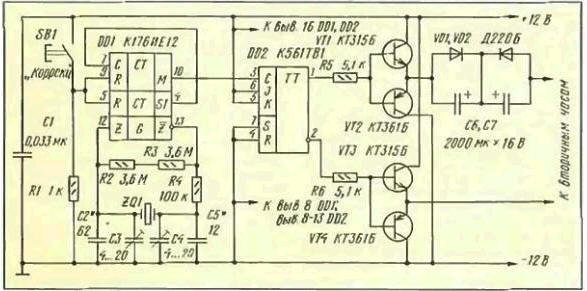
Encyclopedia of radio electronics and electrical engineering / Clocks, timers, relays, load switches Small organizations and firms would like to use secondary clocks with 24 V stepper motors, but this requires a "clock station", ensuring their work. The purchase of such a station is far from affordable for every enterprise, besides, its maintenance requires certain costs. Radio amateurs-designers can help in solving this problem. They are quite capable of building a simple "clock station" designed for a small number of secondary clocks. One of the options for such a station has already been described by S. Alekseev (see "Radio", 1985, No. 10, pp. 44,45). In the article published below, readers are offered a description of another primary quartz clock, in which the problem of changing the polarity of the 24 V pulse voltage supplied to the secondary clock is otherwise solved. The station is designed to connect five secondary clocks. Its schematic diagram is shown in the figure. The minute pulse generator is made on a DD1 chip and a ZQ1 quartz resonator at a frequency of 32 Hz, connected according to a typical circuit [768]. From the output of the DD1 chip (pin 1), minute pulses are fed to the counting input of the trigger DD10. The flip-flop changes its state every time a positive voltage drop appears at its input. The direct and inverse trigger outputs are connected to the bases of the transistors VT2, VT1 and VTZ, VT2 connected in a bridge circuit. The bridge reverses the polarity of the voltage applied to the secondary clock motors depending on the state of the trigger. With a single state of the trigger, transistors VT4, VT1 are open and through the circuit C4, C6 [7]. windings of electric motors of the secondary clock current pulse flows. When the state of the trigger changes, transistors VT2 open. VТЗ and the polarity of connecting the power source to the load also changes. Diodes VD1, VD2 eliminate the possibility of polarity reversal of capacitors C6, C7. Capacitor capacitances are selected depending on the number of secondary clocks connected to the device, achieving reliable control of their course. The diagram shows the capacity for the case of connecting five hours. A rechargeable battery of ten D-0,55 cells is used as a power source. used in portable radios. Any other 12V battery will work. During operation, the battery must be recharged with a current of approximately 10 mA. For safety reasons, a low-power mains transformer should be used in the charger.
The effect of mains interference can be significantly reduced by winding the screen winding and ensuring its reliable grounding. Additional noise reduction is achieved with the help of a choke included in the breaks of the positive and negative wires connecting the rectifier and the battery. Its windings can be wound simultaneously with two mounting wires on a ferrite ring M2000NM. The dimensions of the ring should be such that it accommodates 10 ... 15 turns. The rectifier output and the battery must be shunted with capacitors with a capacity of 0,033 μF or more with a low parasitic inductance. In particular, they should not be paper. You can read more about this in [3]. The average value of the current of discharging and charging the battery is estimated by experimentally setting the energy balance between them. To do this, in the first months of operation of the clock station, it is necessary to observe the voltage of the battery. It should be equal to 13 V. which corresponds to 60% of its charging capacity. If a noticeable tendency to decrease or increase in battery voltage is detected, increase or decrease its charging current by selecting a ballast resistor. When connecting the clock to a network with obviously unstable voltage, it is recommended to install a current stabilizer instead of a ballast resistor. It is performed according to the scheme shown in Fig. 7, a article by S. Semushin "Power sources and their application" (see "Radio", 1978. No. 2, p. 44). A voltage of 26 V should be applied to the input. In order to set the zener diode current V1 to no more than 8 mA, it may be necessary to select the resistance of the resistor R8. Resistors R1-R6 are more convenient to replace with a variable resistor. Instead of transistors GT403G and GT308V, KT814V and KT361V are suitable, respectively. The use of this stabilizer guarantees the invariance of the established balance of charging and discharging the battery. With a steady voltage on the battery of 13 V, you can "forget" about the existence of the clock, without forgetting, however, to timely transfer them to summer and winter time. Literature
Author: L. Maslyaev, St. Petersburg
Machine for thinning flowers in gardens
02.05.2024 Advanced Infrared Microscope
02.05.2024 Air trap for insects
01.05.2024
▪ Unmanned aerial vehicles with biohull ▪ Milk began to drink in the Urals ▪ Electricity puts out the fire ▪ Super stable laser makes GPS more accurate
▪ section of the site Winged words, phraseological units. Selection of articles ▪ article In the hanged man's house they don't talk about the rope. Popular expression ▪ article Who hides his head in the sand? Detailed answer ▪ article Design Engineer. Job description ▪ article Simple ADC - prefix to a PC. Encyclopedia of radio electronics and electrical engineering ▪ article Postcard-boomerang. Focus Secret
Comments on the article: Vladimir Unfortunately, not all secondary watches have enough spirit - the voltage is a bit low! Come across HF, so-called. Type 110. They have two last. conn. coils of 20500 turns of wire. 0.1 mm and a very weak magnet, not even from ARMCO, but from a simple, barely magnetized steel. It happens that 24 volts is not enough for them to step. I even had to give 300 volts from a separate rectifier, and only then did they react to bipolar impulses. Do not be afraid: the resistance is huge, the impulse is short, nothing will burn!
Home page | Library | Articles | Website map | Site Reviews
www.diagram.com.ua |

 Leave your comment on this article: