|
|
ENCYCLOPEDIA OF RADIO ELECTRONICS AND ELECTRICAL ENGINEERING Electric heater temperature stabilizer. Encyclopedia of radio electronics and electrical engineering
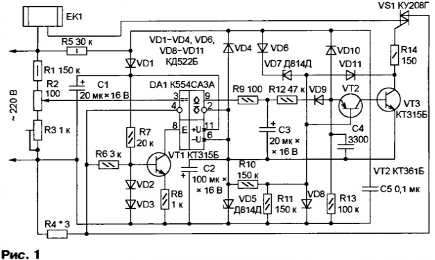
Encyclopedia of radio electronics and electrical engineering / Power regulators, thermometers, heat stabilizers The temperature sensor in the proposed device is ... the electric heating element itself, the resistance of which depends on temperature. Since no special sensor is required, thermal stabilization is achieved without interfering with the design of the heater. In most electrical appliances used to heat a liquid, a good thermal connection is provided between the heated medium and the electric heating element. Therefore, by maintaining the temperature of the element constant, it is possible to stabilize the temperature of the liquid with sufficient accuracy in many cases. In some cases, such a stabilizer will save you from big troubles. For example, it will eliminate the dangerous overheating of an electric boiler that is turned on without water or left unattended, as a result of which the water boils away. The proposed device can replace a failed bimetallic thermostat in an electric iron, where the thermal resistance of the heater-sole is small. This achieves a higher accuracy of maintaining the temperature of the sole. Stabilization of the temperature of an electric heater operating under conditions of weak and unstable heat extraction (for example, heating the air in a room) does not guarantee the constancy of the ambient temperature, however, it increases the reliability and safety of the heater operation. Due to the absence of a sensor, the described stabilizer is suitable for high-temperature heating devices (for example, muffle furnaces), where it eliminates the need to control the temperature using expensive thermocouples. The scheme of the device is shown in fig. one.
A pulse generator is assembled on transistors VT2 and VT3, which opens the triac VS1 - the switch of the EK1 heater - at the beginning of each half-cycle of the mains voltage. This minimizes switching noise and power spent on triac control. Diodes VD1 and VD4 serve as rectifiers, and zener diodes VD5 and VD7 serve as voltage regulators for the supply voltage of the DA1 comparator and generator. The resistance of the heater EK1 forms a measuring bridge with resistors R1-R4, to the diagonal of which the inputs of the comparator DA1 are connected. The resistance and power of the resistor R4 should be approximately 0,5% of the corresponding parameters of the heater. The voltage drop across this resistor is 1,1 ... 1,2 Veff. With the help of resistors R2 and R3, they ensure that the bridge is balanced at the nominal or maximum allowable (depending on the task being solved) temperature of the heater. The balance analysis occurs when the triac VS1 is open and only in negative half-cycles of the mains voltage, when the transistor VT1 is closed by a negative voltage taken from the resistor R4, which allows the comparator DA1 to work. If the temperature, and hence the resistance of the heater, is higher than the set values, the level at the output of the comparator becomes low when it is turned on. Capacitor C3 quickly discharges through resistor R9. A negative voltage is supplied to the emitter of transistor VT2 through resistor R12 and diode VD9, blocking the pulse generator. The generator will resume operation only after charging the capacitor C3 through the resistor R12. In the next negative half-cycle of the mains voltage after the resumption of the generator, the comparator DA1 will again "check" the resistance of the heater EK1, and depending on the result, the generator will either continue to work or will be blocked again. Therefore, when overheating, the voltage to the heater is supplied only for a short time with pauses depending on the time constant of the R12C3 circuit. If the temperature is lower than the set temperature, the heater operates continuously. If the heater power is more than 1 kW, it is necessary to replace the VS1 triac of the type indicated in the diagram with a more powerful one (for example, TS106, TS112 series). To control such a triac, a current amplifier may be required, assembled according to the circuit shown in Fig. 2.
A printed circuit board measuring 40x32,5 mm, shown on a 2:1 scale in fig. 3 is designed specifically for such a powerful version of the device. If an additional amplifier is not required, the elements VT4, VD12 and R15 are not installed, and the inductor L1 is replaced with a jumper. Triac VS1 is located outside the board and must be provided with a heat sink suitable for the switching power. Each of the D814D zener diodes can be replaced by a pair of low-voltage zener diodes connected in series with a total stabilization voltage of 12 ... 15 V, for example, KS162A, KS168A, KS175A. The printed conductors and pads required for such a replacement are shown in fig. 3 are shaded. The role of zener diodes for a voltage of approximately 7 V can also be performed by the emitter junctions of the KT315B transistors (emitter - cathode, base - anode of an equivalent zener diode). Having mounted all the elements, except for the VD9 diode, a heater is connected to the stabilizer and connected to the network. First of all, they check the voltage between terminals 11 and 6 of the comparator DA1, which should be in the range of 24 ... 30 V. If, in the presence of pulses on the collector of the transistor VT3, the triac VS1 does not open or comes off only in positive half-cycles of the mains voltage, in the stabilizer without an additional amplifier reduce the resistance of the resistor R14. If it was not possible to achieve reliable opening of the triac in this way, you will have to install the elements shown in Fig. 2, and pick up the resistor R15. Next, the output of the resistor R12, right according to the diagram, is temporarily connected with a jumper to the "common" wire (for example, with the cathode of the VD3 diode) and make sure that using the trimmer resistor R3, two voltage values \u3b\u5bare set on the capacitor CXNUMX: almost zero and close to the stabilization voltage of the zener diode VDXNUMX . The device is finally adjusted after removing the temporary jumper and installing the VD9 diode. Having transferred the variable resistor R2 to one of the extreme positions and after waiting for a time sufficient to establish the thermal regime, the temperature of the heater or the heated medium is measured. The same measurements are repeated with several positions of the control knob for the resistor R2. Based on the results obtained, the resistor can be equipped with a scale calibrated in temperature values. The boundaries of the regulation interval are corrected with a tuning resistor R3, replacing, if necessary, the variable resistor R2 with a similar one of a different rating. By changing the scheme of the measuring bridge in accordance with Fig. 4 and making a few more minor changes, on the same printed circuit board, you can assemble a conventional thermal stabilizer with a temperature sensor - a thermistor.
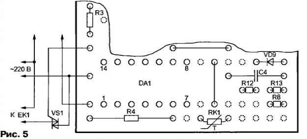
A fragment of the drawing of the placement of elements for this version of the device is shown in fig. 5. Everything outside of it remains the same as in fig. 3.
The dotted circles show the holes freed from the outputs of the elements VT1, VD2, VD3, C3 that are no longer needed, from the output of the engine of the trimmer (now constant) resistor R3 and from one of the wire jumpers. Resistors R7 and R9 are replaced with jumpers, and the contact pads intended for resistor R6 are connected to the terminals of the thermistor RK1 with a nominal (measured at a temperature of +25 ° C) resistance of 10 ... 100 kOhm. The value of the resistor R4 is chosen equal to the resistance of the thermistor RK1 at the average temperature of its regulation interval. Author: V.Kaplun, Severodonetsk, Ukraine
Machine for thinning flowers in gardens
02.05.2024 Advanced Infrared Microscope
02.05.2024 Air trap for insects
01.05.2024
▪ When boarding a flight, show a working gadget ▪ Digital Video Camera with Built-in Hard Disk Drive ▪ Solar panels are thinner than cobwebs
▪ section of the site Metal detectors. Article selection ▪ article Finance, money circulation and credit. Crib ▪ Okra article. Legends, cultivation, methods of application ▪ article The balloon does not burst and bursts. Focus Secret
Home page | Library | Articles | Website map | Site Reviews www.diagram.com.ua |


 Arabic
 Bengali
 Chinese
 English
 French
 German
 Hebrew
 Hindi
Hindi Italian
 Japanese
 Korean
 Malay
Malay Polish
 Portuguese
 Spanish
 Turkish
 Ukrainian
 Vietnamese


 Leave your comment on this article: