|
|


 Arabic
 Bengali
 Chinese
 English
 French
 German
 Hebrew
 Hindi
Hindi Italian
 Japanese
 Korean
 Malay
Malay Polish
 Portuguese
 Spanish
 Turkish
 Ukrainian
 Vietnamese
|
ENCYCLOPEDIA OF RADIO ELECTRONICS AND ELECTRICAL ENGINEERING Clock thermometer. Encyclopedia of radio electronics and electrical engineering
Encyclopedia of radio electronics and electrical engineering / Power regulators, thermometers, heat stabilizers On the LED indicator of this device, the readings of the current time periodically change to the value of the ambient temperature at the location of the sensor - a conventional semiconductor diode. The device does not contain chips that require programming. Schematic diagram of the watch-thermometer is shown in fig. 1. The "clock" part is built on the well-known K176IE18 (DD4) and K176IE13 (DD6) microcircuits. About the principle of their operation and features of the application can be found, for example, in [1].
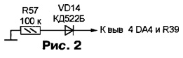
The thermometer is based on the KR572PV6 (DA4) microcircuit - a double-integration ADC, in many respects similar to the well-known KR572PV2 and KR572PV5. The main differences are in the increased accuracy of converting voltage to code (4,5 decimal places) and output circuits designed to connect a dynamic digital indicator. BCD codes of the digits of the conversion result alternately appear at the outputs B1, B2, B4, B8. Each digit is accompanied by a high logic level at the corresponding output D1 (highest decimal digit, not used in the device under consideration) - D5 (least significant digit). Pulses at the STB output mark the moments of digit change. The logic level at the POL output indicates the polarity of the result: 1 - positive, 0 - negative. The clock pulses with a frequency of approximately 4 kHz, necessary for the operation of the DA120 chip, are fed to its CLK input from the generator on the elements DD2.3 and DD2.4. On the KR142EN19A (DA3) microcircuit, a 2,5 V voltage regulator is assembled for the measuring circuits of the thermometer. Capacitor C11 prevents parasitic generation. Using resistor R21, the current (approximately 0,14 mA) is set through the temperature sensor - diode VD12. The voltage on the diode, at a constant current, linearly dependent on temperature, is fed to the IN input of the DA4 microcircuit. A voltage equal to the voltage across the VD26 diode at a temperature of 12 DC is applied to its input IN + from the engine of the tuning resistor R0 - approximately 600 mV. The reference voltage of 200 mV at the input Uref of the ADC is set with a tuning resistor R28. It is this value (in absolute value) that the potential difference of the inputs IN+ and IN- would have reached at a sensor temperature of ±100 °C. Practically, the range of the measured temperature is -60...+99,9 °С. The R22C15 circuit protects the ADC input from noise and interference. Capacitor C19 is designed to store the reference voltage. Capacitor C16 and resistor R39 are elements of the integrator. Capacitor C18 is included in the automatic zero correction circuit of the ADC. Diode VD12 is shunted by capacitor C13 to eliminate interference with a frequency of 50 Hz, which can significantly distort the readings. You can read about the operation of such a thermometer in [2]. The K561LS2 (DD7) microcircuit - four AND-OR elements with common strobing inputs - alternately connects two sources of indicator digit selection signals to the indicator node: outputs T1-T4 of the DD4 microcircuit in time indication mode or outputs D2-D5 of the DA4 microcircuit in temperature indication mode. The signals from the outputs of the DD7 elements control the transistors VT8, VT10, VT13, VT14, which alternately turn on the indicators HG1-HG4. At the inputs of DDI - a BCD to seven-element converter - the signals from the outputs B1, B2, B4, B8, STB of the DA4 microcircuit are fed through the repeaters of the DD8 microcircuit. The outputs of the DD1 microcircuit are also connected to its (converter DD6) inputs. However, the control signal applied to the input V DD6 and the inputs E and Z DD8 allows only the outputs of one of these microcircuits to be active, turning the outputs of the other into a passive (high-impedance) state The passive state of the outputs of the DD6 chip does not affect the time counting process in any way. As a result, when log. 1 at pin 5 of the DD5 counter, the HG1-HG4 indicators display the temperature, and with a log. 0 - time. The CN input of this counter receives second pulses from the output 51 DD4 chips, so every 4 s the output level 5, and with it the display mode, change. When the contacts of the SA1 switch are opened, the counter will stop in the state in which it was at the moment of opening. Closing the contacts of switch SA1 will resume the periodic change of modes. Through current amplifiers on transistors VT1-VT7, the output signals of the DD1 code converter are fed to the anodes of the HG1-HG4 indicators. In the temperature indication mode, the "extra" senior digit of the indicator is extinguished by the signal arriving at the input K of the converter DD1, formed by the element DD3.1. The signal from the output of the element DD3.2 at a negative temperature includes the element g on the indicator HG1 - the minus sign. Element DD3.3 and transistor VT11 control the LEDs HL1 and HL2. In temperature display mode, both LEDs are off. In the time indication mode, the HL2 LED always flashes at a frequency of 1 Hz, and HL1 - only when the SA1 switch is closed. The second group of contacts of this switch, closing the circuit of the emitter HA1, allows the sound signal of the alarm clock to sound. Since the input 12 of the DD8 microcircuit is connected to a common wire, in the active state (in the temperature indication mode) the high logic level from the output 11 of this microcircuit through the key on the VT12 transistor turns on the h element on the HG3 indicator - a decimal point between the digits of units and tenths of a degree. Resistors R48-R56 are needed to increase the high logic level voltage at the outputs of the DA4 chip. Resistors R3, R13-R16 are load resistors in the output circuits of the open-source DD4 microcircuit. The power supply unit of the device consists of a transformer T1 and two full-wave rectifiers. One of them (on diodes VD3 and VD4) provides a voltage of +12 V to power the anode circuits of the HG1-HG4 indicators. From it, with the help of an integral stabilizer DA1, a voltage of +5 V is obtained to power the microcircuits of the device. From the voltage of the second rectifier (on diodes VD5, VD6), using the integrated stabilizer DA2, a voltage of -5 V is obtained, which is necessary for the ADC chip DA4. As a transformer T1, you can use any network with two secondary windings for 9-12 V at a load current of at least 300 mA. The DA1 and DA2 microcircuits will replace any integrated stabilizers, respectively, positive (for example, KR1157EN502A) and negative (for example, KR1168EN5) voltage of 5 V. In the extreme case, the negative voltage stabilizer can be parametric on the KS156A zener diode. The current consumed in the -5 V circuit does not exceed 3 mA. Backup battery GB1 - three galvanic cells of standard size AA connected in series. It is designed to keep the clock running in the absence of mains voltage. In this case, the battery voltage is supplied through the VD13 diode only to the "clock" microcircuits DD4 and DD6. So that the rest of the microcircuits left without power do not affect the mentioned ones, resistors R11, R43-R46 are connected in series in the circuits connecting them, and the resistor R31 in the backup power mode maintains a low logic level at the input V of the DD6 microcircuit. Resistor R23 provides recharging of the GB1 battery during mains operation. The author's copy of the watch-thermometer is assembled in a plastic watch case from the radio designer "Electronics". The parts are installed on several fiberglass boards and connected mainly by hanging insulated wires. Access to the axes of the tuning resistors R26 and R28 is through the holes in the rear of the case. Instead of the SC10-21YWA LED indicators indicated in the diagram, you can use any others with a common cathode that are suitable in size and color of the glow. LEDs HL1, HL2 are placed in the gap between the indicators HG2 and HG3. As transistors VT8, VT10, VT13, VT14, you can use any p-pn silicon structures with a current transfer coefficient of at least 180 and a maximum collector current of at least 300 mA. When choosing a replacement, pay attention to the residual collector-emitter voltage in saturation mode, which significantly affects the brightness of the indicators. For KT530A transistors, it does not exceed 0,13 V. Sound emitter HA1 - small-sized electromagnetic from an imported alarm clock. Instead, you can successfully use a dynamic head with a voice coil resistance of at least 30 ohms. Import analogues of the KR572PV6 chip - ICL7135 or TLC7135. Some instances of such ADCs suffer from a "skewed" characteristic - the results of converting a positive and an equal negative voltage in absolute value are slightly different (not counting the level at the POL output). Eliminate skew with a diode-resistor circuit connected as shown in fig. 2.
The adjustment of the clock part of the device is described in detail in [1]. And to calibrate the thermometer, the temperature sensor (diode VD12) is placed in melting ice or snow and the trimming resistor R26 achieves a zero reading on the LED indicator. If this fails, select the value of the resistor R25. Then, by lowering the sensor into hot water with a temperature controlled by a reference thermometer, resistor R28 sets the corresponding value on the indicator. The brightness of the indicators HG1-HG4 and LEDs HL1, HL2, if necessary, can be increased or decreased by selecting the values of the resistors R4-R10, R30, R36. In conclusion, I would like to share my experience of installing a temperature sensor outdoors. It should be located as far as possible from the windows and walls of the house, well blown by the wind, but be sheltered from direct sunlight. The best place is the outer part of the balcony railing. A horizontal wooden bar with a section of 30x30 mm and a length of approximately 500 mm is attached perpendicular to it. At the end of the bar, far from the balcony, at an angle of 30 °, a sun visor with dimensions of 300x300 mm is installed from plywood with a thickness of at least 10 mm. Under the visor at a distance of 40 ... 60 mm from the center of its lower surface, a VD12 diode is placed, having previously placed it in a moisture-proof capsule of a suitable volume, for example, from under the medicine. The opening in the capsule, through which the connecting wires are brought out, should be sealed. Literature
Author: V. Surov, Gorno-Altaisk
Machine for thinning flowers in gardens
02.05.2024 Advanced Infrared Microscope
02.05.2024 Air trap for insects
01.05.2024
▪ World's most powerful tidal turbine launched ▪ Fujifilm X-T2 mirrorless camera ▪ New product labeling technology ▪ Smart scales determine the speed of propagation of the pulse wave
▪ site section Spectacular tricks and their clues. Article selection ▪ article Fundamentals of life safety. Crib ▪ article Who is Bolivar? Detailed answer ▪ Article Strychnos poisonous. Legends, cultivation, methods of application ▪ article Instant freezing of water. Focus Secret
Home page | Library | Articles | Website map | Site Reviews
www.diagram.com.ua |


 Leave your comment on this article: