|
|
ENCYCLOPEDIA OF RADIO ELECTRONICS AND ELECTRICAL ENGINEERING Small power regulator. Encyclopedia of radio electronics and electrical engineering
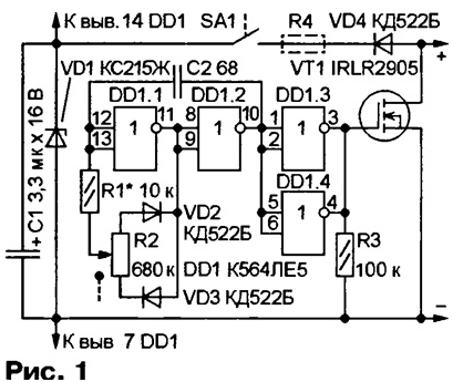
Encyclopedia of radio electronics and electrical engineering / Power regulators, thermometers, heat stabilizers Based on a powerful switching field-effect transistor, for example, IRLR2905, you can assemble a small-sized power regulator for heating (soldering iron, heater) or lighting devices (incandescent lamps for portable or stationary lights powered by a car battery). A diagram of a possible variant of such a device is shown in Fig. 1. The principle of its operation is based on changing the turn-on time of the field-effect transistor.
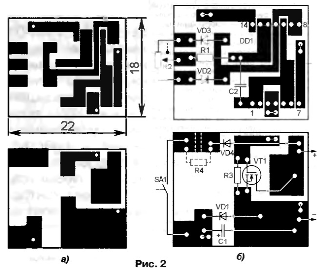
On the elements DD1.1, DD1.2, a rectangular pulse generator is assembled. Their repetition frequency is about 15 kHz, the duty cycle can be adjusted from 1,01 to 100 with a variable resistor R2. Elements DD1.3, DD1.4 are used as a buffer amplifier, from the output of which the control pulses are fed to the gate of the field-effect transistor VT1. With a high (more than 1,5 ... 2 V) logic level at the outputs of these elements, the resistance of the transistor channel decreases to 0,027 Ohm. At this moment, a current flows through the load, the value of which depends on its resistance and the supply voltage. When a low logic level is set at the outputs of the elements, the transistor closes and no current flows through the load. By varying the ratio between the time the transistor is on and the time it is on, the average current through the load can be adjusted. The regulator is connected in series with the load, observing the polarity. With the ratings and types of elements indicated in the diagram, the supply voltage can be in the range from 4 to 14 V. It is turned on by supplying the supply voltage to the DD1 microcircuit through the SA1 switch, combined with the regulator - variable resistor R2. In this case, during the time when the field-effect transistor is closed, capacitor C4 is charged through the VD1 diode and the switch contacts. When the transistor is open, the microcircuit is powered by the energy stored by the capacitor C1. Since the current consumed by the microcircuit is small, the voltage across the capacitor is approximately equal to the supply voltage. Zener diode VD1 limits the supply voltage of the microcircuit. The fact is that according to the technical conditions, it should not exceed 15 V, but when the transistor closes, an EMF of self-induction occurs in the wires connecting the device to the load and the voltage across the capacitor C1 can exceed this value. With long connecting wires, this EMF can be significant, therefore, in series with the switch SA1, you will have to turn on the resistor R4 with a resistance of several kilo-ohms. By the way, this resistor is also necessary if the supply voltage is more than 15 V. In the regulator, you can use K564LA7, 564LE5, 564LA7 microcircuits, diodes of the KD521, KD522 series. Resistor R2 - SPZ-ZvM (with a switch), the rest - MLT, S2-33, R1-4, capacitor C1 - K53-1, K53-1A, K53-18 or small-sized for surface mounting, C2 - K10-17-1 . The regulator is assembled on a printed circuit board made of double-sided foil fiberglass, a sketch of which is shown in fig. 2a. Details are placed on both sides (Fig. 2,b), printed conductors of different sides are connected by wire jumpers through the holes.
The wires connecting the regulator to the load and the power supply should be as short as possible, with a length of more than a few centimeters, they must be twisted to reduce the inductance. Establishing the regulator is reduced to the selection of resistors R1 and R4. To do this, it is connected in series with the load and in parallel with the contacts of the switch (they must be open, for which a strip of thick paper is placed between them), a milliammeter is connected. By adjusting the load power with a variable resistor R2, the voltage across the capacitor C1 is controlled, which should be approximately 0,5 V less than the supply voltage. If it decreases at the maximum load power, R1 must be replaced with a resistor of greater resistance, and if, on the contrary, it turns out to be more than the supply voltage and reaches the stabilization voltage of the zener diode VD1, then you may have to install a resistor R4 (in this case, from a printed conductor, to which the output of the cathode of the diode VD4 is soldered, the area limited in Fig. 2b by dashed lines is removed). Finally, the need to turn on the resistor R4 is determined by measuring the current consumed by the regulator in the entire range of supply voltages. If it does not exceed a few milliamps, the resistor R4 can be omitted. Otherwise, it must be selected in such a way that this current does not exceed 10 mA. With a supply voltage of more than 15 V, the resistance of the resistor (in ohms) must be at least (Upit-15) / 0,01. With a load current of more than 5 A, the transistor must be fixed by soldering (low-melting solder) on a heat sink - a copper plate with a thickness of 0,5 ... 1 mm and an area of several square centimeters. Author: I. Nechaev, Kursk
Machine for thinning flowers in gardens
02.05.2024 Advanced Infrared Microscope
02.05.2024 Air trap for insects
01.05.2024
▪ Scotland's wind farms are overworking ▪ Smart windows based on the octopus organism ▪ Fujifilm and Panasonic develop an organic image sensor
▪ section of the Radio Control website. Article selection ▪ article Children, kitchen, church. Popular expression ▪ article Where did the Indians come to America from? Detailed answer ▪ article Programmer 1C. Job description ▪ article Thermoelectricity. Encyclopedia of radio electronics and electrical engineering
Home page | Library | Articles | Website map | Site Reviews www.diagram.com.ua |


 Arabic
 Bengali
 Chinese
 English
 French
 German
 Hebrew
 Hindi
Hindi Italian
 Japanese
 Korean
 Malay
Malay Polish
 Portuguese
 Spanish
 Turkish
 Ukrainian
 Vietnamese


 Leave your comment on this article: