|
|


 Arabic
 Bengali
 Chinese
 English
 French
 German
 Hebrew
 Hindi
Hindi Italian
 Japanese
 Korean
 Malay
Malay Polish
 Portuguese
 Spanish
 Turkish
 Ukrainian
 Vietnamese
|
ENCYCLOPEDIA OF RADIO ELECTRONICS AND ELECTRICAL ENGINEERING Capacitive relay for irrigation of mycelium. Encyclopedia of radio electronics and electrical engineering
Encyclopedia of radio electronics and electrical engineering / Home, household, hobby When growing mushrooms artificially in a greenhouse, it is required to maintain a certain humidity of the substrate with mycelium, watering it with small portions of water and avoiding waterlogging. Watering should begin as soon as the drops of water remaining from the previous one dry. Technically, this can be done using a capacitive relay that reacts to the presence of drops. The relay controls a solenoid valve that allows water to enter the irrigation system. The capacitive relay should allow the supply of water at a lower substrate moisture content, and prohibit it at a higher one, i.e., have a hysteresis. Otherwise, watering will be too frequent, the rattling of the water valve, its incomplete opening and closing is not excluded. Hysteresis is easy to provide using an electromagnetic relay, the actuation and release currents of which are not equal. But at high humidity, mechanical contacts are unreliable, so it is preferable to control the valve with an electronic key, and provide hysteresis, for example, due to positive feedback. The prototype of the capacitive relay, the circuit of which is shown in fig. 1, served as the design of I. Nechaev ("Radio", 1988, No. 1, p. 33). The device described there on a CMOS microcircuit with resistors up to 6 MΩ turned out to be completely inoperable in the conditions of an environment characteristic of a greenhouse with high humidity. In the proposed version, a K155LAZ microcircuit of the TTL structure is installed, the resistance of the resistors is significantly reduced. There are manual adjustments of the response level and the width of the hysteresis zone. For electrical safety reasons, the relay is designed to be powered by 24 V AC, approved for use in greenhouses.
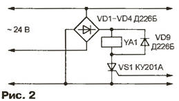
The moisture sensor of the mycelium is four wires twisted into a bundle in polyethylene insulation with a diameter of 0,5 mm (for copper). Suitable wires can be removed from the CCI telephone cable. A piece of bundle 4,5 m long is wound on a frame measuring 180x160 mm from insulating material. One end of the segment is isolated - covered with molten bitumen and wrapped with plastic wrap. The wires at the other end are connected in pairs and connected to a capacitive relay installed nearby, but above the range of irrigation nozzles. Since the dielectric constant of water is very high, droplets, settling on the sensor wires, increase the capacitance between them from approximately 300 to 600 pF. A symmetrical multivibrator is assembled on the elements DD1.1 and DD1.2, which, as the test has shown, works more reliably than an asymmetric one. The multivibrator generates rectangular pulses with a frequency of 50 kHz. A differentiating circuit R1.2C5 is connected to the output of the DD4 element. Since the capacitor C4 forms a capacitive voltage divider with the capacitance of the sensor Cx, the amplitude of the differentiated pulses based on the transistor VT1 depends on the amount of moisture deposited on the sensor wires. Capacitor C3 is separating. On the emitter of the transistor VT1, only the tops of the pulses of positive polarity and approximately triangular shape stand out. The cutoff threshold depends on the bias voltage supplied to the base of the transistor VT1 through resistors R3 and R4. As the threshold decreases, the amplitude and duration of the pulses increase. A similar effect is observed with a decrease in the capacitance of the Cx sensor. At the output of the element DD1.3 - rectangular pulses of a low logic level, the duration of which depends on the position of the trimmer resistor R6, the humidity of the sensor and the magnitude of the feedback voltage supplied through the resistor R3. At a low level at the output of the element DD1.3, the capacitor C7 is discharged through the diode VD6, at a high level, it is slowly charged through the resistor R9. The capacitance of the capacitor C7 is chosen large enough so that it does not have time to fully charge or discharge. The average value of the voltage across it is approximately inversely proportional to the duration of the pulses. If the voltage on the capacitor C7 (taking into account the voltage drop in the base-emitter section of the transistor VT2) is below the switching threshold of the element DD1.4, the high logic level voltage from the output of this element is supplied through the resistor R12, the emitter follower on the transistor VT3 and the resistor R14 to the control electrode trinistor VS1. The trinistor, included in the diagonal of the VD1-VD4 diode bridge, opens and closes the power circuit of the YA1 solenoid valve. Watering is allowed. Part of the output voltage of the DD1.4 element, the removable shift of the tuning resistor R13, serves as a positive feedback signal that creates the necessary hysteresis. As the mushroom substrate is moistened, the capacitance of the Cx sensor increases. This leads to a decrease in the amplitude of the pulses based on the transistor VT1 and an increase in the voltage across the capacitor C7. When sufficient humidity is reached, the high voltage level at the output of the DD1.4 element is replaced by a low one, the trinistor VS1 closes and the YA1 valve stops water from entering the irrigation system. The considered option is designed for the YA1 valve, controlled by alternating voltage. If the valve or other actuator is powered by direct current, the power circuits of the capacitive relay can be assembled according to the circuit shown in fig. 2.
A half-wave rectifier is assembled on the VD5 diode, capacitors C5, C6 and resistor R7. The stabilizer on the transistor VT4 provides a voltage of 5 V at its output to power the DD1 chip. The printed circuit board of the capacitive relay and the location of parts on it are shown in fig. 3. The device uses resistors MSC capacitors BM and MBM, oxide capacitors K50-6, and C5 and C6 are installed outside the board. The VT4 transistor is equipped with a heat sink with an area of 20 cm2. With a small (less than 3 W) power of the irrigation valve, there is no need to remove heat from the thyristor VS1.
When setting up the relay, you should select the capacitor C4, the capacitance of which should be approximately one and a half times the capacitance of the dry sensor. The response threshold is regulated by a tuning resistor R6, and the hysteresis (the difference between the response and release thresholds) is R13. If the optimal mode of operation is achieved only when these resistors are set to their extreme positions, the values of the resistors R3 and R4 should be changed. Author: Yu.Egorov, Moscow
Machine for thinning flowers in gardens
02.05.2024 Advanced Infrared Microscope
02.05.2024 Air trap for insects
01.05.2024
▪ Espressif ESP32-WROVER WiFi Modules for IoT Voice Applications ▪ Fluid that saves energy for 20 years ▪ The secret of adaptation of the Colorado potato beetles is revealed
▪ section of the site Application of microcircuits. Article selection ▪ article Pour out the beauty and harmony of the world. Popular expression ▪ article Who Invented Cosmetics? Detailed answer ▪ article Human Resources Manager. Job description ▪ article Pen-flashlight. Encyclopedia of radio electronics and electrical engineering
Home page | Library | Articles | Website map | Site Reviews
www.diagram.com.ua |


 Leave your comment on this article: