|
|


 Arabic
 Bengali
 Chinese
 English
 French
 German
 Hebrew
 Hindi
Hindi Italian
 Japanese
 Korean
 Malay
Malay Polish
 Portuguese
 Spanish
 Turkish
 Ukrainian
 Vietnamese
|
ENCYCLOPEDIA OF RADIO ELECTRONICS AND ELECTRICAL ENGINEERING Electronic security of the village. Encyclopedia of radio electronics and electrical engineering
Encyclopedia of radio electronics and electrical engineering / Safety and security Recently, cases of intruders entering garden plots have become more frequent. In this regard, the role of the protection of holiday villages is increasing. The described security system consists of a plurality of transmitters that issue an individual code in case of an alarm, and a receiver that indicates the number of the triggered transmitter. The receiver can be located, for example, at the watchman. The code of the village is also encrypted in the transmitted information, so you can use several security systems in close proximity without mutual interference with each other. The pages of amateur radio publications describe many electronic sensors and security devices designed for indoor use. Most often, the alarm is given by a siren located in the same room. Sometimes this is enough - one of those present will respond to an electronic warning, but at uninhabited objects, security electronics must be supplemented with a channel for addressing the alarm signal. As a rule, radio is used in this capacity. Such a communication channel was described, for example, in the article "The radio channel of the security alarm" ("Radio", 1995, No. 1 and 4). However, to protect a group of objects (the same dachas left for the winter), multi-channel systems are needed. It is convenient to implement such a radio network according to the "star" scheme (Fig. 1). Here 1, 2, N - radio transmitters on protected objects, differing from each other in that each of them emits its own radio signal in the alarm mode; Pr - a radio receiver, on the display of which the code of the protected object appears when the sensors on this object are triggered.
The described radio network operates on one of two frequencies: 26945 kHz or 26960 kHz. In standby mode, its transmitters do not go on the air. In the alarm transmission mode, the transmitter broadcasts its personal radio code, repeats it several times and turns off, leaving the air clear. Transmission duplication is necessary to improve reliability, since in this system there is no feedback channel for acknowledgment. The code message is represented as a binary sequence, for example, 101010101110011, where one corresponds to the presence of a carrier, and zero corresponds to a pause of pure ether. And if n is the number of digits in such a sequence, then the number of variants of signals of the nth length will be equal to 2P. Each digit corresponds to a time interval - familiarity. The number of digits is assumed to be 15 (Fig. 2). Character 0 is always occupied by one. This is the starting radio pulse, which facilitates decryption. The remaining familiarity (1 - 14) - information. They place a personal code - one of 16384 (214) possible.
The code package is conditionally divided into two groups. In familiar places 1 - 8 place the code of the security system itself (the code of the village). This part will be common to all codes belonging to the same security system. In familiar places 9 - 14 place the object code. Although any number from the range {0, 1, 2, 255} (28=256) can be taken as the alarm system code, it is not recommended to use too simple, for example, 0 (binary 00000000) or 255 (binary 11111111). The object code can be any number from {0,1,2.....63} (26=64), i.e. the maximum number of protected objects is 64. On fig. 3 shows a schematic diagram of an encoder that controls the transmitter in accordance with the above principle of constructing a radio code. The encoder is based on switches DD2 and DD3, the X inputs of which are connected either to a common wire (so zero is entered in the corresponding familiarity of the code) or to the positive output of the power source (there will be one in this familiarity).
On the elements DD6.1 and DD6.2, a trigger is assembled, which is transferred to the active state by the front of a single pulse at the output D, generated by the security system of the object. At the same time, a low level occurs at pin 6 of the DD6.3 element and the generator on the elements DD6.3, DD6.4 starts to work. Since the time to enter the oscillator mode with quartz frequency stabilization can be quite large, the R3C1 circuit and the DD5.4 element are introduced to provide a delay. After 1,4 s after the start of the generator, a low level will appear at the output of the DD5.4 element, which will allow the passage of pulses through the DD5.2 element. Which of the switches (DD2 or DD3) will be activated depends on the signal at input S: the K561KP2 switch is activated when this input is low. In this case, the outputs of another switch are transferred to a high-impedance state that does not affect the output signal. Which of the eight inputs X of the involved switch will be connected to the output depends on the signals at its address inputs 1, 2, 4. Switch DD2 will turn on first. Its input X1 is connected to the positive output of the power source so that the first pulse corresponds to one (this is the starting pulse). Then the first six characters of the code will be generated. With the advent of high-level counter DD29 at output 1, switch DD2 will go into the passive state, and DD3 into the active state. Thus, the final eight digits of the code will be formed. With the selected frequency of the ZQ1 quartz resonator (32768 Hz), the duration of the familiarity is approximately 2 ms (more precisely, 1,953 ms), and the total duration of the code transmission is about 30 ms (15 familiar spaces of 2 ms). Having generated the first code message, the encoder will not allow the passage of the second one: the high level that occurs at the output 210 of the counter DD1 will block the element DD4.2 and set a low level at its output (pin B). So, alternately alternating a code message with a zero pause of the same duration, the counter DD1 will be in a state where a high level first appears at its output 213 and then disappears. The decline of this pulse will generate a short high-level pulse at the output of the DD4.3 element (its duration is 0,3 ms), which will return the trigger DD6.1, DD6.2 to its original state. This completes the encoder cycle. The R6C3 circuit is designed to reset the trigger and counter DD1 to its original state when the power is turned on. It is easy to verify that, working in this way, the encoder will generate eight code parcels, spending 0,5 s on their generation. This will happen if the pulse duration at the output D is less than 0,5 s. With a longer pulse, the trigger DD6.1, DD6.2 will remain active and the encoder will continue its work - it will generate the next eight code packets. This will continue until a low level appears at pin D. In other words, if the transmission of only eight radio codes seems insufficient, their number can be increased to 16, 24, 32, etc., by increasing the duration of a single pulse at pin D of the encoder. In alarm mode, a high level will appear at the output of element DD5.1 (pin A). This signal will turn on the transmitter master oscillator only for the time of generating radio codes, leaving him sufficient time to enter the mode. The radio transmitter circuit is shown in fig. four.
The frequency of the master oscillator, assembled on the transistor VT1, is set and stabilized by the quartz resonator ZQ1. Transistor VT4 is the key in the generator power circuit: at a high level at pin A, the transistor VT4 will be open to saturation, and at a low level it will be securely closed. The amplifier-manipulator of the transmitter is assembled on a transistor VT2. In the amplification mode, this stage only works when the transistor VT5 is open to saturation, i.e., at a high level at pin B. The amplified high-frequency signal is taken from the part of the L1C3C4 oscillatory circuit tuned to the operating frequency. The output amplifier is assembled on a transistor VT3. Since the transistor VT3 operates with a cutoff, the power consumption of the output stage without high-frequency excitation is close to zero. As is known, when the transmitter is manipulated too "rectangularly", out-of-band components appear in the radiation spectrum. Their level can be significantly reduced by tightening the fronts and decays of the modulating pulses. For this purpose, the capacitor C10 is used (the duration of the decline depends on its capacitance) and the inductor L5, the inductance of which determines the duration of the front. Diode VD1 dampens the voltage surge on L5 that occurs when the transistor VT5 is closed. The SB1 button is used to switch the transmitter to continuous emission mode: when the button is pressed, both control transistors - VT4, VT5 - will be opened. The printed circuit board of the transmitter and encoder is shown in fig. 5.
The board is made of double-sided foil fiberglass with a thickness of 1,5 mm. The foil under the parts is used only as a common wire and screen. In places where conductors are passed, protective circles with a diameter of 1,5 ... 2 mm should be etched in it (not shown in Fig. 5). Connections to the common wire foil of the terminals of capacitors, resistors, etc. are shown in black squares. Squares with a bright dot in the center show the "grounded" pins of the microcircuits and wire jumpers that pierce the board for connecting certain fragments of printed wiring to the common wire. It is not necessary to mount the encoder and transmitter on a common board. The board can be cut (Fig. 5), and the necessary connections can be made with a four-wire cable (A, B, + Upp, Common), the length of which can reach up to 10 m. All resistors in the encoder are MLT-0,125. Capacitors C1, C3, C4 - K10-176; C2, C6 - KM-6; C5 - any oxide of a suitable size. An encoder assembled without errors does not require adjustment. The transmitter uses MLT-0,125 resistors. Capacitors C1 - C4 - KD-1; C5, C6 - KM-6 or KM-5; C7 - KD-2; C8 - K10-176. Chokes L3, L4 - D-0,1. The inductor L5 is wound on a magnetic circuit made up of three ferrite rings K7,5x4x2,5 (ferrite - M2000). It contains 150...200 turns of wire PEV-2 0,07. The design of the loop coil L1 and its location on the board are shown in fig. 6 (coil L2 differs only in the absence of a tap). Coil L1 has 13 turns (n1=7, n2=6) wound turn to turn with wire PEV-2 0,48, and L2 - 11 turns wound with wire PEV-2 0,56. The coils are tuned with M3x8 carbonyl cores.
The quartz resonator of the transmitter can be simply soldered. But as experience shows, its actual resonant frequency is often quite different from the one marked on the case. The selection of a resonator will be simplified if sockets from the connector are soldered into the board, designed for pins with a diameter of 1 mm (Fig. 7)
To establish the transmitter, a 50-ohm equivalent of the antenna is connected to the antenna connector (two MLT-0,5 100 Ohm resistors connected in parallel) and a high-frequency voltmeter. By pressing the SB1 button (continuous radiation mode), set the maximum voltage on the antenna equivalent by adjusting the coils L1 and L2. The transmitter can be configured without a voltmeter, if you take an incandescent lamp with a voltage of 2,5 V for a current of 0,068 A as an antenna load. The maximum brightness of its glow will correspond to the correct setting. You can make sure that the transmitter is operating at a given frequency, either by the frequency meter (it is connected to the antenna equivalent), or by the S-meter of a remote CB radio station - the readings of its S-meter should reach a pronounced maximum in the channel corresponding to selected frequency. The transmitter's out-of-band emissions are judged by the readings of the station's S-meter in adjacent channels. An oscilloscope is required to check the correct operation of the entire transmission path. Not necessarily high-frequency, C1-94 is also suitable if a detecting head is made for it (Fig. 8). By connecting an oscilloscope with such a head to the antenna equivalent and setting the standby mode with a sweep of 20 ... 30 ms, you can control the envelope of the transmitted message.
So, if the code 101010101110011 is set in the encoder, then in response to the triggering pulse, the oscillogram shown in Fig. 9.
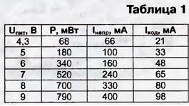
By observing this waveform, you can refine the transmitter setup. The best setting will correspond to the maximum amplitude of the pulses (due to the resistive divider in the detection head, it will be close to 1/2 of the amplitude of the high-frequency signal). On the screen of a high-frequency oscilloscope connected directly to the antenna equivalent, without a detecting head, the oscillogram will look like that shown in Fig. 2. The power given by the transmitter to the antenna (P), the current consumed by the cipher transmitter in the continuous emission mode when the SB1 button is pressed (Incon). the current consumed in the mode of continuous code emission (Icode) and the dependence of these values on the supply voltage Upit are shown in Table. 1. The current in the code emission mode was measured under the condition that the code package contains 9 "units".
The current consumed by the device in standby mode is less than 5 μA. Let's take Upit = 6 V and select the power source. The battery can be made up of four galvanic cells (soldering is required), capable of briefly delivering a current of 160 mA (this is with a margin). For example, you can use AA elements (316) with a capacity of 450 ... 850 mAh. However, such elements have significant self-discharge. Among the electrochemical sources, the self-discharge current of which is comparable to the current consumed in standby mode, there is, perhaps, only one group - lithium sources. Many of them retain almost their entire capacity (85%) up to 5...10 years. The battery can be made up of individual elements (the EMF of a lithium cell, depending on the characteristics of electrochemistry, is from 1,5 to 3,6 V), but there are also ready-made ones, for example, DL223A (voltage - 6 V, capacity - 1400 mAh, dimensions - 19,5x39x36 mm) and DL245 (voltage - 6 V, capacity - 1400 mAh, dimensions - 17x45x34 mm). Powering a transmitter with a lithium source can be left unattended for several years. The option of food from the five-six-element rechargeable battery recharged from the power supply network, or from the solar battery is possible. Short-term power consumption and the ability of many batteries to work in forced modes will allow the use of batteries with a very small capacity - 50 ... 100 mAh. A schematic diagram of a radio receiver that receives signals from radio network transmitters is shown in fig. 10. The radio frequency amplifier (URCh) is made on field-effect transistors VT1 and VT2. Both RFID circuits (L2C1 and L3C2) are tuned to the frequency of the radio network. The gain of the URF depends on the resistance of the resistor R4: with a larger resistance, the gain is less.
The output circuit of the URC is inductively connected to the inputs of the DA1 microcircuit, which converts the high-frequency signal into an intermediate frequency signal. At a transmitter frequency of 26960 kHz and a local oscillator frequency of 26495 kHz, a 2 ± 465 kHz signal will appear at the output of the ZQ5 bandpass filter, preserving all the features of the high-frequency signal manipulation. The intermediate frequency amplifier (IFA) is included in the DA2 microcircuit, which contains an AM detector and AGC elements. The IF gain is regulated by the resistor R11. The considered receiver stages are practically no different from the stages of a conventional communication or broadcast receiver. But the next stage - the DA3 comparator - is specific: it converts signals from analog to discrete form - into zeros and ones. The receiver is mounted on a printed circuit board (Fig. 11) made of double-sided foil fiberglass. Antenna socket X1 (CP-50-73) is mounted directly on the board.
Fixed resistors - MLT-0,125, tuning resistors R4 and R11 - SPZ-38a. Capacitors C1, C2, C6 - C8 - KD-1; C3, C15, C18 - K10-176; C5, C11, C12 - KM-6; C4, C9, C13, C17 - any ceramic suitable sizes; C14 - K53-30. The contour coils are wound on the same frames as the transmitter coils. Coils L2 and L3 each contain 17 turns of PEV-2 0,33 wire wound tightly in a row. In the coupling coils L1 and L4 - 3 turns each, they are wound over the contour from the side of their "cold" (HF) ends with a PEVSHO wire with a diameter of 0,15 ... 0,25 mm. Resistor R12 may need to be selected: with a receiver supply voltage of 9 V and its possible decrease, the supply voltage of the DA2 microcircuit should remain within 5 ± 0,5 V. The receiver is tuned to a signal from a nearby transmitter loaded with a 50-ohm dummy antenna. It is necessary to set the mode of continuous code emission (connect input D to the positive output of the power source). The oscilloscope is connected to the output of the DA2 chip (pin 9). By tuning both receiver circuits, the maximum amplitude of a single pulse is achieved on the oscilloscope screen. In a digital signal receiver, it is very important to correctly set the comparator threshold. In order for the signal at its output to be assigned either to a low or to a high level, the condition |U3-U4|>Upit/KU must be met, where U3 and U4 are the voltage at inputs 3 and 4 of the comparator; KU - its gain (for K554SAZ KU=150 103). From here | U3 - U4| >60 µV. In the voltage range IU3 - U4I < 60 μV, the K554SAZ comparator behaves like a highly sensitive operational amplifier: its output voltage can be any in the range from 0 to 9 V. In order for the noise in the communication channel not to interfere too much with the operation of the receiver, the threshold IU3 - U4I is set so that in the absence of a signal, the voltage at the output of the comparator DD3 (pin 9) almost always remains equal to the supply voltage. "Almost always" is due to the fact that the noise signal has a probabilistic nature and its individual emissions can, generally speaking, be anything. But the probability of an outlier appearing that overlaps the set threshold will be the smaller, the greater the threshold itself. In other words, by setting the threshold, a compromise problem is solved: on the one hand, it should be large enough so that noise failures are rare, on the other hand, the threshold should not be such that the useful signal disappears under it. Observing on the oscilloscope screen (at the DA2 output) the passage of single code pulses against the background of noise, you can set the desired threshold "by eye". So, for example, as in Fig. 12, a. True, the signal-to-noise ratio here is clearly small, and noise failures will most likely be quite frequent. In the situation depicted in Fig. 12b, they will be much rarer, since the signal-to-noise ratio is about twice as high here.
There are two ways to increase the signal-to-noise ratio: either by increasing the signal level from the weakest transmitter, installing, for example, a more efficient transmitting antenna on this object, or by reducing the noise level, although the possibilities here are not so great (narrowing the receiver bandwidth, reducing the level of its own noise). But the general principle is clear: the comparator sets the threshold I Uz - U4 | = Umin / 2, where Umin is the weakest single signal. In this case, the effect of noise on the passage of both zero and weak single signals will be approximately the same. The comparator threshold depends on the resistance of the resistor R15. Since the voltage at the DA2 output (pin 9) in the "clean air" mode is close to zero, then at R15 = 3 MΩ we have the threshold |U3-U4| \u13d UpitR13 / (R15 + R75) \u9d 2 mV. However, this does not mean that it remains unchanged during operation: when a carrier or intense interference appears in the channel, the voltage at pin XNUMX of DAXNUMX increases (shifts to + Upit) and the set threshold automatically decreases. Peculiar requirements in receivers of this kind are also imposed on the AGC system. On the one hand, it must be fast, so that the receiver can use the windows of "clean" air among the interference (we recall that only 32 ms is needed for the signal to pass through); on the other hand, the AGC should be slow, preserving the linearity of the channel, not allowing it to be clogged with long-term interference of a small (in relation to the useful impulse) level. In the described receiver, the AGC controls only the gain of the first stage of the IF (change in the supply voltage). Its inertia depends primarily on the capacitance of the capacitor C10. But there are other possibilities, as shown in Fig. 13 fragments of the block diagram of the K157XA2 microcircuit.
The digitized signal is fed to the decoder, the circuit of which is shown in Fig. 14. It is based on a 16-bit shift register (DD3, DD4), which should contain the code received from the air. The signals necessary for this form the counters DD1 and DD2. The generator built into the DD1 chip operates at the frequency of the "clock" quartz resonator ZQ1. The same frequency was used in the formation of the transmitter cipher signal.
The high level signal at the output 210 of the counter DD2 sets the decoder to standby mode (the passage of a meander with a frequency of 32768 Hz from the output K of the DD1 chip is blocked by the DD8.1 element). In this state, the decoder remains until the output of the element DD7.1 high-level pulse - the start pulse of the code radio signal or an interference pulse. On the front of this pulse, a short single pulse is formed at the inputs R of all counters and registers, which puts them in their original position. The duration of this pulse is determined by the parameters of the integrating circuit R4C1. But since, after the reset pulse, the lock DD8.1 will also be removed (now the output 210 DD2 is low), then after about 1 ms a high level will appear at the output 25 of the counter DD2. The shift register will shift towards the higher digits (in Fig. 14 - down) the contents of all its digits (while there are only zeros in them) and enter a unit or zero into the first digit - what will be at that moment at the input D (vyv. 7) DD3. This offset reading will continue until DD210 output 2 goes high, stopping the decoder. As an example, in fig. 15 shows the procedure for entering the code (1) 01010101110011 into the shift register (start pulse in parentheses).
At the end of the decoder operation, when the sixteenth shift pulse passes, pins 2 DD3 and 5, 4, 3, 10, 13, 12, 11 DD4 should have a security system (OS) code, and pins 4, 3, 10, 13, 12 and 11 DD3 - code of the protected object. The received OS code will be read by the VD2-VD9 diode decoder. And if the code matches the code set by the diodes (here - 01010101), a high level will appear at the output of the DD8.3 element. This signal will block the reset of the registers (their shift is already blocked) and turn on an alarm acoustic signal, thereby drawing the operator's attention to the HG1 display, on which the object code will be reproduced. You can reset the record and return the decoder to the control mode only by pressing the SB1 button. If there is some other number in the bits allocated for the OS code, then after 32 ms the decoder will return to standby mode without notifying anyone about the work done. Of course, the OS code may be different. The principle of its decoding is simple: all bits of the register, in which there should be zeros, are connected to the anodes of the diodes. Obviously, a low level on the resistor R8 will occur only if there are zeros on all the anodes of these diodes. Units are compared in a similar way: a high level at the input of the DD8.2 element will occur only if there are units on all cathodes of the "single" diodes. If both groups are accepted correctly, a high level will appear at the output of the DD8.3 element - a sign that the OS code in the register matches the one typed in the diode decoder. Resistor R2 - KIM-0,125, the rest - MLT-0,125. Capacitors C2, C3 - KD-1; C1, C4, C5 - KM-6; C6 - any oxide of suitable sizes. The SB1 button is an MP7Sh microswitch riveted to the board. Dynamic head BA1 must have a power of at least 0,5 watts. The decoder is assembled on a printed circuit board made of double-sided foil fiberglass 1,5 mm thick (Fig. 16).
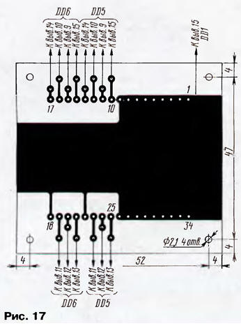
The HG1 liquid crystal indicator is mounted on a separate board with dimensions of 60x55 mm, which is made of one-sided foiled fiberglass 1,5 mm thick (Fig. 17). It is connected to the decoder board with thin flexible conductors in fluoroplastic insulation.
In the author's version, the boards of the radio receiver, decoder and liquid crystal indicator were assembled into a single unit (Fig. 18) using four studs with an M2 thread (made from a bicycle spoke) and tubular speakers. A case was made, in the front panel of which there were cutouts for the scoreboard and a dynamic head, and C3adi - holes for the coaxial connector jack and power wires. An SB1 button drive (short countersunk head rivet) was installed in the upper part of the case. In the author's version, the case had dimensions of 122x62x52 mm.
Almost any 9 V AC adapter can serve as a power source for the receiver, but in case of a power outage, it must be backed up by a galvanic or rechargeable battery, which is switched on as shown in Fig. 19. The current consumed by the receiver in standby mode is 6,5 mA, in alarm mode it is less than 45 mA.
In conclusion - about the antennas. At protected sites located close to the receiving center (up to 1 km), you can use small-sized antennas from portable CB radio stations, at remote sites - full-sized antennas of this range (see, for example, the article "Wire CB antennas" in "Radio ", 1996, No. 9, p. 9). In any case, it is better to have the antenna hidden. The antenna of the receiving center must be full-sized. It is better if it is a loop vibrator or an antenna with autotransformer matching (antennas that have almost zero DC resistance are less sensitive to out-of-band interference). It may turn out that the gain of the receiving path will remain too high even after taking measures to reduce it in the VRF and IF. Then the antenna is connected through a high-frequency divider (Fig. 20, Table 2), which reduces the signal level at the antenna input of the receiver to an acceptable level. Since it is not necessary to accurately divide the signal level, the values of RA and RB are rounded up to the nearest nominal value.
The use of radio frequencies, as well as the acquisition and operation of radio transmitters, must be carried out on the basis of the relevant permits of the bodies of the State Radio Frequency Service. Author: Yu.Vinogradov, Moscow
Machine for thinning flowers in gardens
02.05.2024 Advanced Infrared Microscope
02.05.2024 Air trap for insects
01.05.2024
▪ LD39100 - Series 1A LDO Regulators from STMicroelectronics ▪ Japan's Smart Agriculture Abroad ▪ Solar Impulse 2 completes round-the-world flight ▪ Over 300 types of ice identified
▪ site section Tone and volume controls. Article selection ▪ article Burning yourself, shine to others. Popular expression ▪ article How do glasses correct vision? Detailed answer
Home page | Library | Articles | Website map | Site Reviews
www.diagram.com.ua |


 Leave your comment on this article: