|
|


 Arabic
 Bengali
 Chinese
 English
 French
 German
 Hebrew
 Hindi
Hindi Italian
 Japanese
 Korean
 Malay
Malay Polish
 Portuguese
 Spanish
 Turkish
 Ukrainian
 Vietnamese
|
ENCYCLOPEDIA OF RADIO ELECTRONICS AND ELECTRICAL ENGINEERING Timer for charging the battery of the electric shaver. Encyclopedia of radio electronics and electrical engineering
Encyclopedia of radio electronics and electrical engineering / Clocks, timers, relays, load switches Manufacturers of some household appliances powered by batteries (for example, electric shavers) recommend monitoring the charging time by the clock to avoid damage to them. It is advisable to entrust this work to the timer. The design proposed in this article can be used in other cases when a timer with an upper countdown limit of several hours is needed. Schematic diagram of the timer, which was developed for the Kaiser V5-541FC electric shaver by Mikma. shown in fig. 1. It is powered by a voltage source of about 10 V, which includes a diode bridge VD3, a zener diode VD2, capacitors C4 and C3, resistors R7 and R8. A single vibrator with the required pulse duration is assembled on the DD1 chip, and a thyristor optocoupler U1 is used to connect the load to the network.
When the timer is connected to the network, a short pulse is generated at the output of the differentiating circuit C1R2R3, which is fed to the input S of the high-order bits of the counters of the DD1 microcircuit and sets them to a single state. At the output 15 of the DD1 chip, there is a high logic level, the open transistor VT1 shunts the optocoupler LED, and the load is de-energized. The bridge current VD3 flows through the zener diode VD2, the transistor VT1 and the emitting element of the LED HL1 with a red glow. The latter lights up and signals the absence of charging. The high logic level signal through the diode VD1 is fed to the input Z of the DD1 chip and disables the operation of the generator. When you press the SB1 button, all triggers of the counters of the DD1 chip are set to zero, the transistor VT1 closes. The current of the VD3 rectifier bridge starts to flow through the LED of the thyristor optocoupler U1 and the emitting element of the HL1 LED with a green glow. The optocoupler opens and connects the load (shaver charger) to the mains. Current. passing through the emitting LED of the optocoupler. has a pulsating character and reaches its maximum value of 20 mA at the moments when the mains voltage passes through zero. At the same time, a generator assembled on three inverters of the DD1 chip and elements R4 and C2 starts working. The generation frequency is about 1.5 Hz. The pulse period at output 15 of the DD1 chip is 32768 / 1.5 = 21845 s = 6 hours, and after half the period, which corresponds to three hours required to charge the battery, a high logic level signal appears at this output. Transistor VT1 opens, shunts the LED of the optocoupler, and the current through it and the load stops. Now the current of the VD3 bridge will again flow through the emitting element of the HL1 LED with a red glow, which will light up, signaling the end of charging. At the same time, a high logic level signal through the VD1 diode will go to the Z input of the DD1 microcircuit and stop the generator. During interruptions in the mains voltage supply, which do not exceed one hour, the capacitor C3 does not have time to fully discharge, and when the voltage is turned on, the battery charging process will continue. If the interruption in the supply of voltage exceeds the specified time, then when it is turned on again, the counters of the DD1 chip will be set to a single state and the battery will not resume charging, which will prevent its damage due to possible overcharging. With a low probability of interruptions in the mains voltage supply, the SB 1 button and the resistor R1 can be eliminated by connecting the input R of the DD1 chip to the differentiating circuit C1R2R3. and input S - to output 7. In this case, the timer will start immediately after the timer is connected to the network, and in case of large interruptions in the supply of mains voltage, it will resume from zero. All elements of the timer, except for the mains plug, button SB1 and output jacks X1 and X2. mounted on a printed circuit board with dimensions of 42.5x60 mm (Fig. 2).
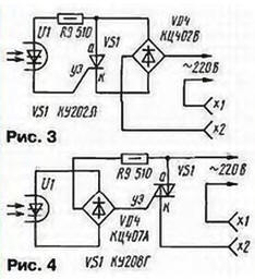
The board is designed to install MLT resistors. capacitors K53-16 (C1). K73-17 (C2, C4), K52-1 (C3). Capacitors C1, C2, C4 are placed parallel to the printed circuit board. Diode VD1 - any silicon low-power, zener diode VD2 - for a stabilization voltage of 9 ... 10 V. Rectifier bridges - for a voltage of at least 50 V (VD3) and 400 V (VD4). Transistor VT1 - any low-power silicon npn structure. In place of C4, any metal-film capacitor can work, for example. K73-16 or K73-17, for a rated voltage of at least 250 V, as well as paper or metal-paper for a rated voltage of at least 400 V. Oxide capacitors - of any type. Button SB1 - MP-1 microswitch with a pusher from the cap of a faulty transistor. The two-color HL1 LED can be replaced by ALS331A, KIPD18A-M, KIPD18B-M, KIPD19A-M, KIPD19B-M, KIPD37A-M, KIPD37A1-M or two conventional LEDs. It is only important that the colors of their glow to indicate the indicated states of the timer correspond to those given, since its operation uses the fact that the voltage drop on the green LED is greater than on the red one. It is permissible to replace the AOU115G thyristor optocoupler with AOU115D, AOU103B, AOU103V or install a triac optocoupler of the AOU160 series with any letter index, while the VD4 rectifier bridge becomes unnecessary. The circuit board, button SB1 and sockets X1, X2 are installed on a plastic box with dimensions 80x64x38 mm from an industrial charger ZU-01M. On one of the walls of this box there were already pins of the power plug. When setting up a timer, a 2 pF capacitor should be placed in place of C330. close the terminals of the capacitors C4 with a jumper and, in parallel with the terminals of the capacitor C3, solder a resistor with a resistance of 10 kOhm (it is necessary for a quick - in one minute - discharge of C3 during the setup process). The timer must be connected to a source of direct or alternating voltage 36 ... 40 V. At this moment, the emitting element of the HL1 LED should flash for a moment with a green glow and light up with red. When you press the SB1 button, instead of red, an element with a green glow will light up, and after about 16 seconds again with red, after which the mode of operation of the HL1 LED should not change. Next, by selecting the resistance of the resistor R4, you should set the time to turn on the load. To do this, put in place the capacitor C2 of the value indicated on the circuit, and connect a DC voltmeter to terminal 12 of the DD1 microcircuit and to the negative terminal of the capacitor C3. By pressing the SB1 button, they count the number of pulses arriving at pin 12 of the DD1 microcircuit in 1 min - they should be 90 or 91. If there are more pulses, it is necessary to increase the resistance of the resistor R4 in proportion to this excess, and if less - reduce. After that, removing the jumper from the terminals of the capacitor C4, check the operation of the timer from the network in the mode of charging the battery of the electric shaver. In this case, at first it is advisable to again reduce the capacitance of the capacitor C2 to 330 pF, and then increase it to 0,33 μF and remove an additional resistor from the terminals of the capacitor C3. The timer can work with other loads. The time it is turned on is easy to change by recalculating the capacitance of the capacitor C2 or the resistance of the resistor R4. To control more powerful consumers, you can use a 220 V electromagnetic relay connected to the output sockets of the timer, as well as a thyristor (Fig. 3) or triac (Fig. 4) key.
Diode bridge VD4 (Fig. 3) must be designed for the required load current. Author: S. Biryukov, Moscow
Machine for thinning flowers in gardens
02.05.2024 Advanced Infrared Microscope
02.05.2024 Air trap for insects
01.05.2024
▪ Netgear Nighthawk M1 Mobile Router ▪ A new way of presenting and mastering curricula ▪ New family of micropower comparators
▪ section of the site Amateur Radio Technologies. Selection of articles ▪ article Twice two - stearin candle. Popular expression ▪ article Why and how did Oedipus go blind? Detailed answer ▪ Article Hairdresser. Job description
Home page | Library | Articles | Website map | Site Reviews
www.diagram.com.ua |


 Leave your comment on this article: