|
|


 Arabic
 Bengali
 Chinese
 English
 French
 German
 Hebrew
 Hindi
Hindi Italian
 Japanese
 Korean
 Malay
Malay Polish
 Portuguese
 Spanish
 Turkish
 Ukrainian
 Vietnamese
|
ENCYCLOPEDIA OF RADIO ELECTRONICS AND ELECTRICAL ENGINEERING The thermometer of the increased accuracy with the DS18S20 sensor. Encyclopedia of radio electronics and electrical engineering
Encyclopedia of radio electronics and electrical engineering / Power regulators, thermometers, heat stabilizers A temperature measuring device based on an ATmega8515 microcontroller and a DS18S20 temperature sensor is proposed, which is characterized by a simple circuit and design with increased measurement accuracy. Today, many different temperature sensors are produced, both analog and digital. However, many analog sensors have a significantly non-linear dependence of the output parameter on temperature (thermistors), the signals of others (thermocouples) must be significantly amplified before use. All of them often require that the manufactured temperature meter be calibrated against a reference thermometer in order to eliminate the systematic error. Digital sensors are usually calibrated at the factory and have a linear temperature scale. A common digital sensor DS18S20 was chosen for use in the device. According to [1], it is capable of measuring temperature in the range from -55 to +125°C. Unfortunately, almost all known thermometers with this sensor (for example, in [2]) do not use the ability to obtain temperature values from it with a resolution of less than 0,5 °C. This is apparently due to the need to read additional information from the sensor and perform calculations using a division operation that is difficult for a simple microcontroller. In the proposed thermometer, this possibility is realized. The temperature is measured with a resolution of 0,1 °C, which allows you to more accurately track the trends in its change. Thanks to the use of a 40-pin ATmega8515-16PU microcontroller, the temperature meter circuit shown in fig. 1 turned out to be relatively simple. The DS18S20 sensor (VK1) is connected to the microcontroller via the 1-Wire interface. To control the sensor in the microcontroller, the PE1 output is selected, and the PE0 input receives information from the sensor. The use of two pins instead of one greatly simplified the microcontroller program.
The operation of the 1-Wire interface is based on encoding the logical zeros and ones transmitted over it at certain time intervals. The duration of these intervals is set quite rigidly, so the microcontroller is clocked from a generator stabilized by an external quartz resonator ZQ1 and providing a machine cycle duration of 0,25 μs. Having given the sensor a command to start the temperature measurement cycle, the microcontroller waits for its completion. It then reads from the sensor's internal registers not only the commonly used temperature measured value Tamended with the price of the least significant bit 0,5 оC, but also two correction factors to it. K factor1 (COUNT_PER_C) - number of pulses generated inside the sensor per one degree of temperature. Coefficient K2 (COUNT_REMAIN) - the remainder in the internal counter after counting the integer part of the measured temperature value. The microcontroller performs the calculation of the adjusted temperature value T according to a formula similar to that given in the reference data of the DS18S20 sensor: T = int(Tamended) - 0,25 + (K1 -K2)/K1 The temperature value is output through ports A, B and C of the microcontroller, the outputs of which are connected through current-limiting resistors R2-R9, R12-R25 with the cathodes of the elements of the HG1-HG3 seven-element LED indicators with a common anode. The temperature is displayed from -55 to +99,9 °C. Negative temperature values lying within -55...-10°C are displayed as integers with a minus sign (Fig. 2, a). In the range of -9,9 ... -0,1 ° С, the temperature is displayed with tenths of a degree and a minus sign (Fig. 2,6). Positive values in the range 0...+99,9°С are displayed without a sign with tenths of a degree (Fig. 2, c).
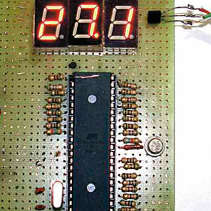
The thermometer is assembled on a fiberglass technological board with metallized holes arranged along a grid with a step of 2,5 mm (Fig. 3). A panel is installed on the board for the microcontroller. Capacitors C1-C3 are ceramic. Installation was carried out on the reverse installation of parts on the side of the board with the MGTF wire. The VK1 temperature sensor can be made remote by connecting it to the board with a triple of twisted wires no longer than 5 m.
The current consumed by the thermometer, depending on the temperature value displayed on the indicators, varies from 50 to 110 mA. When using the microcontroller indicated on the diagram, the thermometer can be powered from any source of constant voltage 4,5 ... 5,5 V. When powered by a battery, it is advisable to replace the microcontroller with ATmega8515L-8PU, which operates at a supply voltage of 2,7 ... 5,5 V, which practically coincides with the allowable supply voltage of the DS18S20 sensor (3 ... 5,5 V). The microcontroller program can be downloaded from ftp://ftp.radio.ru/pub/2014/05/mega8515.zip. Literature
Authors: E. Lukyanenko, N. Nikitina, A. Starykh
Machine for thinning flowers in gardens
02.05.2024 Advanced Infrared Microscope
02.05.2024 Air trap for insects
01.05.2024
▪ Highly sensitive camera will search for extraterrestrial life and dark matter ▪ Interactive panel for classrooms with motion sensors ▪ Methane on Mars is not a sign of life
▪ website section Television. Article selection ▪ article Annibalov (Gannibalov) oath. Popular expression ▪ article Personnel during work on endoscopic diagnostics. Standard instruction on labor protection ▪ article Radio station on 5650-5670 MHz. Encyclopedia of radio electronics and electrical engineering
Home page | Library | Articles | Website map | Site Reviews
www.diagram.com.ua |


 Leave your comment on this article: