|
|


 Arabic
 Bengali
 Chinese
 English
 French
 German
 Hebrew
 Hindi
Hindi Italian
 Japanese
 Korean
 Malay
Malay Polish
 Portuguese
 Spanish
 Turkish
 Ukrainian
 Vietnamese
|
ENCYCLOPEDIA OF RADIO ELECTRONICS AND ELECTRICAL ENGINEERING Retro clock. Encyclopedia of radio electronics and electrical engineering
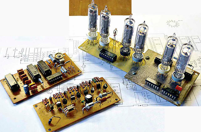
Encyclopedia of radio electronics and electrical engineering / Clocks, timers, relays, load switches The author of the article, having decided to "remember his youth", made an original desktop electronic clock from gas-discharge indicators and other parts produced in the last quarter of the last century. Probably, any radio amateur (especially the older generation) will agree that an electronic clock for him is not just a homemade product, but a product useful for the whole family. At the beginning of his radio amateur activity, each radio amateur (and I, of course, too) collected several hours. But that was a long time ago, when electronic watches, even in the simplest and most primitive case, or even without it, were something amazing... When the industry released the "Start" set in the mid-90s, which contained everything needed for the watch, including the printed circuit board, the watch-making boom broke all records. In our dormitory of the Institute of Radio Electronics, clocks without cases, assembled from it, hung on all the walls. But those days are gone forever. Today, trade offers such a wide selection of the most diverse watches that you can hardly imagine anything original. I won’t say anything about a home-made case comparable to an industrial one. It is not for everyone to make it. That is why I did not plan to take any more watches. However, about a year ago I saw on the Internet a photograph of a watch with IN-16 gas-discharge indicators (Fig. 1). Despite the fact that such indicators have long been obsolete, the watch looked interesting, unusual and very nostalgic. Three circumstances prompted me to take up the manufacture of such watches. First, an interesting look. Secondly, the case is very easy to make. And thirdly, I have had gas-discharge indicators for a long time and were intended specifically for watches. But then I didn’t start making clocks on them, because the Start set appeared with its large and amazing IVL1-7/5 indicator, in comparison with which the gas discharge indicators looked unsightly.
But now the wheel of history has made another turn, watches on gas-discharge indicators began to be considered "retro" and became fashionable. Now the magical orange color and the simple shape of the numbers of gas discharge indicators look original, and even bewitching in the dark. Naturally, the question arose - to assemble a clock on a microcontroller or conventional clock chips? Of course, the clock on the microcontroller has more features. They can show the year, month, and day of the week, they can have multiple alarms, control electrical appliances, and much more. But since I had "retro watches" in mind, I decided that it would be right for them to be "retro" inside as well. Despite the apparent complexity, the designed watch is easy to manufacture and set up, because it is assembled on specialized "watch" microcircuits. Many of these microcircuits are on the shelf - it's a pity to throw them away, but there is nowhere to apply them. If they are not in old stocks, then they are still available for sale and are inexpensive. High-voltage transistors and diodes can be soldered from faulty energy-saving lamps. Therefore, the cost of a set of parts for such watches is minimal. Almost anyone can repeat them. Clock circuits on "clock" microcircuits are well known to radio amateurs. But known designs do not provide indication of seconds, and hours and minutes are displayed on LED or vacuum fluorescent indicators. Therefore, it was necessary to coordinate the "hour" microcircuits with gas-discharge indicators and add a seconds indication block. The result is a device consisting of four boards: time counting (scheme in Fig. 2), indication of hours and minutes (scheme in Fig. 3), high-voltage switches and power supply (scheme in Fig. 4), counting and indication of seconds (scheme in Fig. 5). The input and output circuits of these boards of the same name should be interconnected.
Microcircuits K176IE12 (DD2) and K176IE13 (DD3) are designed specifically for working together in hours. I will not describe in detail the purpose of all the pins of these microcircuits - this information can be found in dozens, if not hundreds of sources. I will dwell only on some that are necessary for understanding the clock circuit and their adjustment by beginner radio amateurs. Chip DD2 generates second and minute pulses. They are fed to the DD3 chip, which contains the counters of minutes, hours and an alarm memory register with a device for turning on the sound alarm at a given time. A quartz resonator ZQ12 is connected to pins 13 and 2 of the DD1 chip at a frequency of 32768 Hz with the elements necessary to work with the internal oscillator of the chip. Such a resonator is called "clock". Capacitor C1 is necessary for fine tuning the frequency of the generator, on which the accuracy of the clock depends. At pin 14 of the DD2 chip, this frequency can be controlled by a frequency counter. The inputs of the initial setting of the counters of the DD2 chip (pins 5 and 9) are connected to the corresponding output (pin 4) of the DD3 chip. When you press the time correction button SB1, the signal from the DD3 chip will reset these counters. It, through the level converter on the transistor VT20, enters the inputs of the initial setting of the counters of units of seconds DD6 and tens of seconds DD8 (Fig. 5). Indication of hours and minutes in the considered device is dynamic. This means that each indicator is turned on only in the time interval when pins 13, 14, 15, 1 of the DD3 chip have the code of the number that should be displayed on this particular indicator. The signals from pins 3, 1, 15, 2 of the DD2 microcircuit, which control the switching on of the HG1-HG4 indicators in turn, are fed to high-voltage switches assembled on transistors VT9-VT12, VT14, VT15, VT17, VT18 (see Fig. 4). These switches apply a high voltage of positive polarity to the indicator anodes. But since they invert control signals, they must be inverted again before being fed to the keys. Inverters DD1.1 - DD1.4 are designed for this (see Fig. 2). At pin 4, the DD2 chip generates second pulses going to its own input C (pin 7). The same pulses through the level converter on the transistor VT19 (Fig. 5) are fed to the input of the seconds counter on the DD6 microcircuit. The signal from output 8 (pin 11) of this counter is input to the counter of tens of seconds on the DD8 chip. The signals from the outputs of the discharges of both counters are fed to high-voltage decoders DD7, DD9 and further to the indicators HG5, HG6. Thus, the indication of units and tens of seconds is not dynamic, but static. Second pulses are also applied to the input of a high-voltage switch on a transistor VT8, which controls the neon lamp HL1. In the final version of the clock, I refused the dot flashing every second, but did not remove the corresponding node from the circuit. It is possible that someone would like to have such a point in his watch. The option I used to add a counter and seconds indicator to the clock has one feature. Since the counters K155IE2 and K155IE4 change their state according to the decays of the input pulses, the switching of seconds occurs half a second later than the switching of minutes by the counter of the DD3 microcircuit. However, this is noticeable only when the 59th second changes to zero. I didn't see this as a disadvantage. Let them think that this is how it should be, because the watch is not ordinary, but "retro". Pin 6 of the DD3 chip is the input of the clock correction signal. The output of the alarm sound signal is pin 7. From it, the signal goes to the power amplifier on transistors VT6 and VT7 and then to the sound emitter HA1. As already mentioned, from pins 13, 14, 15, 1 of the DD3 microcircuit, the digit code enters through level converters (transistors VT1-VT4) to the information inputs of the storage register - the quad D-trigger DD4. Writing to this register occurs according to the signal from pin 12 of the DD3 chip, which has passed through the level converter on the VT5 transistor. From the outputs of the register, the codes of the digits of hours and minutes are fed to the common decoder DD5 (see Fig. 3), the outputs of which are connected to the combined cathodes of the HG1-HG4 indicators of the same name. The conclusions of the unused cathodes of the indicators should in no case be left unconnected, otherwise a parasitic glow of the numbers corresponding to them is possible. The SB1-SB4 buttons and the SA1 pushbutton switch are used to control the operation of the clock (they turn the alarm sound on and off). The SB2 and SB3 buttons are used to set the minutes and hours, respectively, and the SB4 button is used to set the alarm time. When the SB4 button is pressed, the indicators show this time. To change it, you must press the SB2 and SB3 buttons without releasing the SB4 button. The SB1 button allows you to correct the clock, for which it should be pressed a few seconds before the actual end of the current hour. This will stop the time count. The internal minutes and seconds counters of the DD2 and DD3 microcircuits, as well as the counters DD6 and DD8, will be reset to zero. If the number of minutes at the time of stop was less than 40, the value in the hour counter of the DD3 chip will not change, otherwise it will increase by one. On the signal of the exact time, the SB1 button should be released, after which the counting of time will continue. Unfortunately, when the SB1 button is pressed, the number on any indicator remains on. In order not to complicate the watch, I did not make a node for extinguishing all indicators, considering that this cannot be considered a drawback of retro watches. However, such a node can be added to them by assembling it according to the scheme shown in Fig. 24 in [1]. As already noted, in the proposed watch, the indication of hours and minutes is dynamic, and seconds is static. So that the brightness of the HG5 and HG6 indicators does not differ from the brightness of the HG1-HG4 indicators, the values of the resistors R25 and R26 in the anode circuits of the HG5 and HG6 indicators are increased to 150 kOhm. Due to the lack of space in the watch case, I made their power supply according to a transformerless circuit. Therefore, all watch parts are under mains voltage. When establishing them, special care should be taken [2]. If, when repeating the design in the case, there is a place for a step-down transformer, I recommend using a transformer power supply. The secondary winding of the transformer must be designed for a voltage of about 12 V at a load current of 150 ... 200 mA. In this case, the capacitor C8, the resistor R9 and the zener diode VD7 are excluded from the circuit. Another option is to use a remote stabilized switching power supply for 9 or 12 V. Such units are usually similar in design to cell phone chargers, they are used everywhere. When using a 12 V power supply, capacitor C8, resistor R9, diode bridge VD6 and zener diode VD7 are excluded from the circuit. The output voltage of the power supply, observing the polarity, is applied to the capacitor C9. If a 9 V power supply is used, in addition to the elements listed in the previous paragraph, the VT13 transistor, the R14 resistor and the VD9 zener diode are also excluded from the circuit, and the anode of the VD10 diode is connected to the positive terminal of the capacitor C9. The large capacitance of the capacitor C10 allows the clock to run for some time after the mains power is turned off. The VD10 diode cuts off other circuits from the capacitor C10, allowing it to use the stored energy only to power the DD1-DD3 microcircuits. With a capacitance of 2200 uF indicated on the diagram, the clock continues to work for more than 10 minutes. This is quite enough to not only prevent readings from failing, but also, for example, to move the clock from one room to another. In the article [3] there are experimental data on the dependence of the duration of the clock on the capacitance of this capacitor. If you still need backup power, study the article [3] - its author offers several options. And if you do not like the sound of the alarm clock available in the watch, you can assemble another one according to the schemes from [3] and [4]. In [5], there is even a variant of an alarm clock on a UMS musical synthesizer chip [6]. On fig. 6 shows the printed circuit boards on which the clock is assembled. I do not cite their drawings, because both the clock circuit and the printed circuit boards have been repeatedly changed and refined. For example, when I decided to add a seconds indicator to the clock, I did not develop a new board, but simply attached an additional one to the existing board of hour and minute indicators. There were changes in other boards. Since the clock was made in one copy, I did not recycle printed circuit boards, taking into account the changes.
Instead of the K176IE12 chip, you can use the K176IE18, but the scheme for switching it on is different. Instead of the K176LA7 chip in the described clock, it is permissible to use the K176LE5, and no changes to the circuit are required. Just do not forget that such a replacement will become impossible if it is decided to make an indicator blanking unit according to the scheme from article [1]. Instead of a quad D-flip-flop K155TM7, you can use K155TM5. The use of the K155TM7 chip is explained only by the fact that I had it in stock. I installed it in the clock, leaving the inverse trigger outputs free. Many parts can be taken from the electronic ballasts of defective energy-saving lamps. From it is taken, for example, a small-sized oxide capacitor C7. Its capacitance can lie in the range of 2,2 ... 10 microfarads. The transistors ME13003, MJE13005, MJE13007, MJE13009 used in ballasts can be used instead of KT605A. Of the domestic transistors, KT604A is suitable for replacing them. You can also use two K166NT1A transistor assemblies, which will somewhat complicate the development of a printed circuit board, but will reduce its dimensions. Finally, 1N4007 diodes can be taken from faulty ballasts, which will replace all diodes in the clock (except zener diodes). Of these, you can also assemble a diode bridge instead of KTS407A. Of the domestic diodes, other low-power silicon diodes with a permissible reverse voltage of 102 V or more, for example, KD300A, KD104B-KD105D, are suitable as a replacement for KD105B diodes. Diodes KD102A in this case can be replaced by any low-power silicon diodes. If the dimensions of the board allow, instead of the diode bridge KTs407A, you can use KTs402 or KTs405 with any letter indices. Transistors KT315G and KT361G can be replaced by transistors of the same series with any letter indices or other low-power silicon transistors of the corresponding structure with an allowable collector-emitter voltage of at least 15 V. Instead of the KT815G transistor, transistors of the KT815, KT817, KT819 series with any indices are suitable. However, transistors of the KT819 series, for reasons of size, are best used in a plastic case (without index M). Since 5 V is supplied to the input of the 12 V voltage regulator, the VT16 transistor generates a significant amount of heat. Therefore, it must have a heat sink, which can be of any design. For example, an aluminum plate with a thickness of several millimeters and an area of at least 15 ... 20 cm2. Buttons SB1-SB4 - any that fit in the watch case. Instead of the SA1 pushbutton switch, any sliding or lever switch can be used under the same condition. The sound emitter HA1 is a telephone capsule with a resistance of at least 50 ohms. If space in the case allows, you can use a small-sized dynamic head by connecting it through an output transformer from any transistor receiver. In this case, the volume of the alarm signal will increase significantly. The quenching capacitor C8 is composed of three capacitors K73-17 with a capacity of 1 μF for a constant voltage of 630 V, connected in parallel. They can be placed in any free space in the case. Keep in mind that not all capacitors are suitable for quenching. For example, capacitors BM, MBM, MBGP, MBGTS-1, MBGTS-2 [7] cannot be used. If the dimensions of the case allow, you can use capacitors MBGCH or K42-19 for a voltage of at least 250 V or MBGO for a voltage of at least 400 V. The manufacture of the watch case should be approached with all care, since the impression that the watch will make on friends and acquaintances depends on it. Next, I indicate the dimensions of my watch. Naturally, they can be changed. Take a flat, well-polished wooden plank 50 mm wide and 5 mm thick. Saw off two parts 200 mm long and two parts 70 mm long from it. I recommend using a hacksaw with smaller teeth than a hacksaw. Try to cut strictly at a right angle. Then, using any wood glue (for example, PVA), glue the frame. Its outer dimensions are 200x80 mm. For the manufacture of a luminous bottom, a plate of organic glass with a thickness of at least 5 mm is required. Mark a rectangle the size of the resulting frame, and also with a hacksaw, trying to cut strictly at a right angle and without stopping, cut it out. Polish the ends of the plate and glue the resulting bottom to the frame with Moment glue. Install the buttons SB1-SB4 and the switch SA1 on the back wall of the case, drill holes in it for the holder of the fusible insert FU1 and the power cord. Don't forget about the ventilation holes. The most important part of the work is the manufacture of the top cover of the watch from tinted glass. Not everyone can cut such a cover on their own, and even with holes for indicators, so I recommend contacting the nearest glass workshop. They are in any, even the smallest city. They cut glass for windows, mirrors, make aquariums. Just bring the exact dimensions of the cover there and accurately indicate the centers and diameters of the holes for the indicators. A completely satisfactory result will be obtained if the cover is made of organic glass, but the appearance of the watch will be somewhat different. But such a cover can be made by yourself. It is especially worth dwelling on the details that will give the watch made even more charm. These are blue LEDs for illuminating indicators from below and a yellow LED strip that illuminates the rear edge of the bottom of the watch case. There are a great many types of LEDs and strips and almost any can be used. If anyone has any doubt that the LEDs should be exactly blue, and the tape should be yellow, I will not argue. Every man to his own taste. You can experiment with any color or even apply RGB LEDs and RGB tape with remote controlled controllers. Such controllers can be purchased at stores selling electrical goods. HL2-HL7 LEDs are installed under each of the six indicators. They create a beautiful blue luminous halo around the numbers and at the top of the indicators - this effect is clearly visible in the photograph of the watch's appearance (Fig. 7). The LEDs are connected in series and connected through a quenching resistor R24 to the +300 V circuit. By selecting this resistor, the desired brightness of the LEDs is achieved. The LEDs I used have sufficient brightness already at a current of 2 ... 3 mA, so the power dissipated by the resistor does not exceed 0,5 W.
Of course, it would be safer to power the backlight LEDs not with high voltage, but from the output of a low-voltage rectifier - from capacitor C9, respectively, reducing the resistance of resistor R24. I will explain why it was decided to power them from a high-voltage, and not from a low-voltage rectifier. There is already a +300 V voltage on the seconds indicator board, and to power the HL2-HL7 LEDs with low voltage, one more wire would have to be added. The LED strip consists of 50 mm long sections connected in parallel, each of which has two or three LEDs connected in series and a resistor. A 12 V tape is suitable for use in watches. Separate a 200 mm length (four sections) from it and glue it with transparent glue to the rear edge of the bottom of the watch case. Set the desired brightness of the glow with a selection of resistor R12. It should be remembered that the greater the brightness of the glow of the tape, the more current it consumes and the greater should be the capacitance of the quenching capacitor C8. With a capacitance of this capacitor of 3 uF, the current consumed by the tape must not exceed 60 mA, otherwise the voltage across capacitor C9 will drop below 12 V, as a result of which the VT13 transistor will exit the operating mode. With the ratings indicated on the diagram, the tape in my watch consumes just that much and shines quite brightly, although the voltage on it is only 9 V. Literature
Author: A. Karpachev
Machine for thinning flowers in gardens
02.05.2024 Advanced Infrared Microscope
02.05.2024 Air trap for insects
01.05.2024
▪ Biochar will improve the environment ▪ Electronic innovations in service in Iraq ▪ Toshiba N300 8TB Ruggedized Drive ▪ The robot performed before the British House of Lords
▪ section of the site Assembling the Rubik's Cube. Article selection ▪ article Wedding General. Popular expression ▪ article How do we digest food? Detailed answer ▪ article Wild strawberry. Legends, cultivation, methods of application
Home page | Library | Articles | Website map | Site Reviews
www.diagram.com.ua |


 Leave your comment on this article: