|
|


 Arabic
 Bengali
 Chinese
 English
 French
 German
 Hebrew
 Hindi
Hindi Italian
 Japanese
 Korean
 Malay
Malay Polish
 Portuguese
 Spanish
 Turkish
 Ukrainian
 Vietnamese
|
ENCYCLOPEDIA OF RADIO ELECTRONICS AND ELECTRICAL ENGINEERING Aquarium controller. Encyclopedia of radio electronics and electrical engineering
Encyclopedia of radio electronics and electrical engineering / Home, household, hobby Keeping aquarium fish is a rather time-consuming task. It is necessary to turn on the light in time, turn off the compressor at night, supply food in a timely manner, turn off the filter during feeding, etc. To simplify this task, the proposed device was developed. It, unlike other similar ones, is designed to control not incandescent lamps, but LEDs that illuminate the aquarium. I equipped the aquarium with LED lighting, which has a beneficial effect not only on the health and color of the fish, but also on the development of aquarium plants. It was made multi-color, and it can not only be turned on or off, but also sorted through up to fifty states of different durations, differing in brightness and color of the backlight. It is also possible to control the operation of other aquarium devices according to a user-defined program. The indicator displays the current time, the status of the compressor and filter, the average water temperature and the status of the heater, as well as the current heating power as a percentage of the nominal. The machine measures the water temperature with a digital sensor DS18B20, and it is possible to connect two sensors and stabilize the temperature according to the arithmetic average of their readings. There are three program timers for turning the compressor on and off, and three more such timers for turning the filter on and off. You can set the number of feedings per day for the electric feeder, the number of servings of feed per feeding, and set the duration of pauses between servings. The machine consists of two main blocks - a control board and a power supply and switching board, the diagrams of which are shown respectively in fig. 1 and fig. 2. The XP5 connector of the first board is connected to the XP6 connector of the second flat cable. In the assembled device, the signals generated by the microcontroller DD2 at the outputs of PC4 and PC5 are sent to the gates of field-effect transistors VT3 and VT4 that control relays K1, K2. The relay contacts are connected to the blocks XT6, XT7, and power is supplied to the filter and compressor motors through them. Parallel to the relay windings, diodes VD1, VD4 suppressing self-induction voltage surges are installed.
Through the XP2 connector, according to the diagram shown in fig. 3, control buttons SB2-SB5 and LCD HG1 (two lines of 16 characters each) are connected to the microcontroller. Instead of the WH1602C LCD indicated on the diagram, the MT-16S2D or other similar indicator will do. The field-effect transistor VT1 controls the brightness of the LCD backlight according to the microcontroller signals, and the resistor R1 limits the maximum backlight current. A voltage divider for controlling the indicator contrast is assembled on resistors R2-R4.
The DS1307 real-time clock chip (DD1) is powered by a G1 lithium cell that keeps the clock running when the main power is off. This chip is connected to the microcontroller via the I interface.2C. To control the state of the G1 element, part of its voltage through the resistive divider R6R7 is fed to pin 37 of the microcontroller - the input of the ADC built into it. The DD2 ATmega644 microcontroller works with a ZQ2 quartz resonator with a frequency of 20 MHz. Resistor R8 and capacitor C2 form the initial reset circuit of the microcontroller. To transfer it to this state in the event of a program failure, the SB1 button is used. L1C6 - microcontroller ADC power filter. The XP3 connector is designed to connect the microcontroller to the programmer. The microcontroller configuration is programmed in accordance with the table.
Gates are connected to contacts 1 of the XT1-XT3 blocks, and to contacts 2 - the sources of field-effect transistors not shown in the diagram (IRLR024N transistors were used) that control the aquarium backlight LEDs. The XP4 connector is designed for connection according to the scheme shown in fig. 4, electronic feeder "Feeder AF2003", purchased in the online store. When choosing a feeder, you should pay attention that it is without an LCD indicator. The XP1 connector is used to connect the damper actuator located in the aquarium lid under the feeder.
The entire electronic part has been removed from the feeder, leaving only the electric motor (M1 in Fig. 4) and the limit switch SF1. Tracking the rotation of the feeder with the help of the latter, the microcontroller DD2 generates control signals for the field-effect transistor VT5, which turns on and off the motor M1. The motor supply voltage (3 V) is stabilized by the integral stabilizer DA2. The current consumed by the motor is quite large, so a separate source is needed to power it, connected to the XT9 block. I used an LED lighting power supply. The XP7 connector is connected with a flat cable to the XP4 connector on the control board. Capacitor C17 suppresses noise generated by motor M1. Mains voltage 220 V is supplied to block XT4 (see Fig. 2). Reduced to 6 V by transformer T1, the alternating voltage rectifies the diode bridge VD2. The smoothing capacitor C8 is separated from the bridge by the diode VD3, so the voltage across the resistive divider R24R25 is pulsating, from zero to the amplitude value. Part of this voltage is supplied to the base of the transistor VT2, as a result, the transistor closes when the instantaneous value of the mains voltage is close to zero. Pulses with a frequency of 100 Hz from the collector of the transistor VT2 are fed to the input PD2 of the microcontroller. From the rectified voltage smoothed by the capacitor C8 using the stabilizer DA1, a stabilized voltage of 5 V is obtained to power all the nodes of the device. From the PC3 output of the microcontroller, the signal goes to the optotriac U1, which, in turn, controls the triac VS1, which regulates the power of the water heater in the aquarium. The R31C12 circuit suppresses triac voltage spikes. A heater without a built-in thermal relay is connected to the XT8 block. According to the scheme shown in fig. 5, one or two BK5, BK1 temperature sensors installed in the aquarium are connected to the XT2 block. In case of failure of one of them, temperature control continues according to the readings of the remaining one. In the absence or malfunction of both, the water heater is turned off, about which a message is displayed on the indicator.
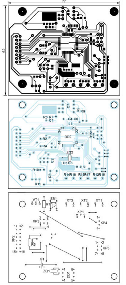
A drawing of the control circuit board is shown in fig. 6. Types of connectors installed on it: XP1 - PLS-3, XP2 - IDC-16MS (BH-16), XP3 - IDC-06MS (BH-06), XP4- WF-04, XP5 - IDC-08MS (BH- 08). The board has 12 wire jumpers and seven surface mount jumpers. For the CR2032 (G1) lithium cell, a BS-02D-1B holder is provided.
The printed circuit board for power and switching is shown in fig. 7. Here the XP6 connector is IDC-08MS (BH-08). Transformer T1 - TPK-2-6V with a secondary voltage of 6 V at a current of 0,4 A. The integral stabilizer 78M05CDT can be replaced by any other for a voltage of 5 V and a load current of at least 0,5 A. Both relays are HK4100F-DC5V-SHG, instead, other relays with a 5 V winding and switching voltage and current limits will be suitable, providing reliable control of the filter and compressor. Capacitors C9, C12 - K73-17 or their imported counterparts.
The feeder control unit (diagram in Fig. 4) is assembled on a printed circuit board shown in fig. 8. The drawing of the board with the SB2-SB5 buttons is not shown due to its simplicity.
When the device is turned on, a splash screen is displayed on the LCD, then an automatic transition to the "Basic" menu takes place. After the first start, you must press, while in this menu, the SB3 "Select" button, hold it until the message "Reset to factory settings" appears on the indicator, and then press the SB2 "Menu" button. The time will be set to 23:59:59 and the date 30:04:13, Tue (Tuesday), and all settings will be reset to zero - this is the default setting in the program. It was experimentally found that if, with a discharged G1 element or its absence, the external power supply of the device is turned off, then after it is turned on, meaningless signs will appear on the indicator. In this case, you should simultaneously press the buttons SB4 "+", SB5 "-" and hold them down for more than two seconds. The DS1307 chip will be reset and the information on the indicator will be updated. By pressing the SB2 button, you go from the "Basic" menu to the "Compressor settings" menu. Here, press the SB3 button and go to the "1st timer" submenu. After that, by pressing the SB2 button, select "On / off timer", "Timer on hours", "Timer on minutes", "Timer off hours" or "Timer off minutes" to change. The selected parameter is changed by pressing the buttons SB4 and SB5. Then, by pressing the SB3 button, you go to the "2nd timer" submenu. All actions in this submenu are the same as described above. The next press of the SB3 button goes to the "3rd timer" submenu and configures it in the same way. With one more press on the SB3 button, all changed parameter values are saved in the EEPROM of the microcontroller and returned to the "Compressor settings" menu. By pressing the SB3 button again, you go from this menu to the "Filter pump settings" menu. There are also three timers that are set like compressor timers, and after setting the third timer, all changed parameters are stored in EEPROM. From the "Filter pump settings" menu, by pressing the SB2 button, go to the "Heater settings" menu. In it, by pressing the SB3 button, you go to the "Heater" submenu and by pressing the SB4 and SB5 buttons turn the aquarium heating on or off. By pressing the SB3 button again, you go to the "Water temperature" submenu and, by pressing the SB2 button, select the lower temperature threshold (below which the heater power will increase) or its upper threshold (above which the heater power will decrease) to change. Then, by pressing the SB3 button, the changed values \uXNUMXb\uXNUMXbare saved in EEPROM and returned to the "Heater settings" menu. From here, when you press the SB2 button, the program goes to the "Lighting settings" menu. In it, by pressing the SB3 button, the submenu "On Time" is opened. By pressing the SB2 button, the hours or minutes of inclusion are selected to change. The selected parameter is changed by pressing the buttons SB4 and SB5. Then, by pressing the SB3 button, you go to the "Stage 1" submenu and by pressing the SB2 button, select "Operating time", "Blue LED PWM control", "Red LED PWM control" or "White LED PWM control" to change. The selected parameter is changed by pressing the buttons SB4 and SB5. The operating time is set in minutes in the range from 0 to 600. The next press of the SB3 button takes you to the "Stage 2" submenu, where all actions are identical to the previous ones. The number of "Stage" submenus can reach fifty, and for each of them you can set your own parameters. For example, a smooth turning on or off of the backlight is implemented by setting a sequence of short stages with a gradually increasing or decreasing brightness of the LEDs. Unconfigured stages remain in the zero state and do not affect the character of the backlight. In the "Stage 50" submenu, pressing the SB3 button causes the message "End of lighting adjustment" to be displayed on the indicator. Then, by pressing the same button, all settings are saved in the EEPROM of the microcontroller and returned to the "Lighting settings" menu. From this menu, by pressing the SB2 button, you go to the "Clock Settings" menu, from where, by pressing the SB3 button, you go to the "Date Settings" submenu. By pressing the button SB2 choose to change the day, month or year. The parameters are changed by pressing the buttons SB4 and SB5. Then, by pressing the SB3 button, you go to the "Day setting" submenu. Having selected here with the buttons SB4 and SB5 the day of the week, from Monday (Mon) to Sunday (Sun), by pressing the button SB3 go to the "Time setting" submenu. In it, by pressing the SB2 button, the hours, minutes and seconds are selected to change, and by pressing the SB4 and SB5 buttons, the desired values \u3b\uXNUMXbare set. By pressing the SBXNUMX button, the entered time is memorized and returned to the "Clock setting" menu. The next press of the SB2 button goes to the "Correction of hours per day" menu, and using the SB4 and SB5 buttons change the number of seconds of the correction (from +9 to -9), which is automatically entered into the clock readings once a day. By pressing the SB2 button again, the set values are stored in EEPROM and go to the "Week clock correction" menu. Here, using the SB4 and SB5 buttons, you set the number of seconds of the correction (from +6 to -6) that is made to the clock readings once a week. With another press of the SB2 button, the correction values \u4b\u5bare saved in EEPROM and go to the "LCD backlight brightness" menu. This parameter can be changed using the SB0 and SB100 buttons within the range of 3-4%. By pressing the button SB5 go to the submenu "Backlight time." and buttons SB3, SB3 set the duration of the LCD backlight (in seconds) after the last press of any button. Then, by pressing the SB4 button, you go to the "Return time" submenu. Buttons SB3 and SBXNUMX change the return delay in the "Basic" menu. The next press of the SBXNUMX button returns to the LCD backlight brightness menu. During this transition, the values of the parameters changed in the considered submenus are saved in the EEPROM of the microcontroller. Pressing the LCD backlight brightness menu on the SB2 button displays on the LCD the value of the voltage of the lithium cell G1 measured by the microcontroller. By pressing the same button one more time, you go to the "View temperature" menu, where you can view the readings of the temperature sensors. If the sensor is disabled, then "1-Off" or "2-Off" will be displayed instead of the temperature value. The next press on the button SB3 go to the submenu "Д1 ROM Cod". Here, when you press the SB2 button, the microcontroller reads the unique serial numbers of the temperature sensors connected to the machine. By pressing the SB4 or SB5 button, you can select any of them for further work as a D1 sensor. By pressing and holding the buttons SB2 and SB5 at the same time, this choice is fixed. Pressing and holding the buttons SB4 and SB5 at the same time erases the information about the choice of sensor D1. Pressing the SB3 button will write the changes to the EEPROM and open the "D2 ROM Cod" submenu. All operations in it are similar to those described, but refer to the D2 sensor. Please note that the same sensor cannot be selected as both D1 and D2. Then, by pressing the SB3 button, you go to the "Sensor polling time" submenu, in which, by pressing the SB4 and SB5 buttons, you set the sensor polling period up to 60 s. With another press on the SB3 button, the set value is saved and returned to the "View temp." menu. Now pressing the SB2 button opens the "Feeder Settings" menu. From it, by pressing the SB3 button, you go to the "T-1" submenu. Using the SB2 button, select the items "On / off", "Timer operation hours", "Timer operation minutes", "Number of servings - number of times the feeder is triggered", "Pause between feeder triggers" to change. The selected value is changed by pressing the buttons SB4 and SB5. By pressing the SB3 button again, all changed parameters are stored and go to the "T-2" submenu. By the next pressing on the same button, they go to the "T-3" submenu, and by one more pressing they return to the "Feeder settings" menu. Operations in the "T-2" and "T-3" submenus are similar to those described for "T-1". Then, by pressing the SB2 button, you go to the "Servo setting" menu, from which, by pressing the SB3 button, you go to the "Open" submenu and use the SB4, SB5 buttons to adjust the position of the damper under the feeder in the open state. Pressing the SB3 button again, go to the "Closed" submenu and adjust the position of the closed damper. The damper positions selected in this way will later be taken during the operation of the electronic feeder. The last press of the SB3 button will write to the EEPROM the values of all changed parameters and return the program to the "Basic" menu. The printed circuit board file in Sprint Layout 5.0 format and the microcontroller program can be downloaded from ftp://ftp.radio.ru/pub/2014/11/aquarium.zip. Author: A. Laptev
Machine for thinning flowers in gardens
02.05.2024 Advanced Infrared Microscope
02.05.2024 Air trap for insects
01.05.2024
▪ Wirepas Pino Automated Wireless Network for IoT ▪ Artificial embryos from stem cells ▪ Organ transplantation without tissue rejection
▪ site section Low frequency amplifiers. Article selection ▪ article Russian literature of the XX century in brief. Crib ▪ article Why do people catch colds more often in the cold season? Detailed answer ▪ article Electrician of a traction substation. Standard instruction on labor protection ▪ Stardust article. Focus Secret
Home page | Library | Articles | Website map | Site Reviews
www.diagram.com.ua |


 Leave your comment on this article: