|
|


 Arabic
 Bengali
 Chinese
 English
 French
 German
 Hebrew
 Hindi
Hindi Italian
 Japanese
 Korean
 Malay
Malay Polish
 Portuguese
 Spanish
 Turkish
 Ukrainian
 Vietnamese
|
ENCYCLOPEDIA OF RADIO ELECTRONICS AND ELECTRICAL ENGINEERING Thermostat on two microcircuits. Encyclopedia of radio electronics and electrical engineering
Encyclopedia of radio electronics and electrical engineering / Power regulators, thermometers, heat stabilizers An important feature of the proposed thermostat is that the heater controlled by it always turns on and off only for an integer number of mains voltage periods. At the same time, a direct current component is not formed in the network, which can adversely affect the performance of transformers and other electromagnetic devices connected to the same network. This device differs from a number of analogues in the absence of hysteresis in the control characteristic, due to which more accurate maintenance of the set temperature is achieved, and in the reduced level of switching noise generated by it. A thermostat operating in this way was described in the article by S. Biryukov "Tsimistor thermal stabilizer" ("Radio", 1998, No. 4, pp. 50, 51), but it has a more complex synchronization unit with the network and creates more interference.
The thermostat circuit is shown in fig. 1. When using a VS1 triac of the type indicated on it, it can control a heater with a power of up to 1 kW. The temperature sensor is the thermistor RK1, which together with the resistors R1-R4 forms a measuring bridge. The trimmer resistor R1 balances the bridge at the temperature that needs to be maintained. The voltage removed from the diagonal of the bridge is supplied to the comparator assembled on the op-amp DA1 without feedback. Resistor R5 sets the operating mode of the op-amp (current consumption, maximum output voltage slew rate). The logic level of the voltage at the output of the comparator becomes low if the temperature of the environment in which the thermistor is located exceeds the specified temperature, or high otherwise. The output signal of the op-amp is fed to the input D trigger DD1.1. And at the input From the same trigger, through the diode VD3 and the voltage divider R6R7, pulses arrive, following the frequency of the network. Switching the trigger is possible only by increasing drops of these pulses at the moments when the instantaneous voltage value on the lower wire of the mains in relation to its upper wire is approximately 6 V and is growing. Therefore, the time intervals between changes in the state of the trigger are always a multiple of the period of the mains voltage, and the changes themselves occur near the transition of the mains voltage through zero. A high logic level of voltage at the output (pin 1) of the DD1.1 trigger means that the heater is enabled, and a low one is disabled. The pulses generated by the VD3R6R7 circuit not only clock the trigger, but also charge the capacitor C2 through the VD1 diode, the voltage on which, limited by the VD1 zener diode to approximately 9 V, is used to power the device microcircuits. On the trigger DD1.2, which is connected according to the scheme of a non-inverting repeater of the signal applied to the input S, a unit for generating pulses for controlling the triac VS1 is made. At this input, in a certain proportion, the signal coming through the diode VD4 from the output of the trigger DD1.1 is summed up, and the voltage rectified by the diode bridge VD5 between electrode 2 and the control electrode of the triac. As a result, a high logic voltage level is present at the output (pin 13) of the DD1.2 trigger only if it is the same at the output of the DD1.1 trigger, and the instantaneous absolute value of the voltage applied to the triac VS1 exceeds approximately 10 V. Even if there is a trigger DD1.1 at the output that allows the signal to turn on the heater, the triac VS1 is closed at the beginning of each half-cycle. At the moment when the instantaneous value of the mains voltage applied to it through the heater reaches 10 V, the level at the input S and the output of the trigger DD1.2 will become high, the transistor VT1 will open and the triac control circuit will be closed. After a period of time required to open the triac, the voltage between its electrodes will drop to several volts. As a result, the voltage level at the input S of the trigger DD1.2 and its output will also become low. Having opened the triac and the impulse that is no longer required will end. But the triac will remain open until the end of the half-cycle, when the value of the current flowing through it becomes less than the holding current. Due to the fact that the duration of the control pulse is automatically maintained to the minimum sufficient to open the triac, the efficiency of the device increases. In the following half-cycles, the described processes are repeated until, as a result of heating the thermistor RK1, the level at the output of the trigger DD1.1 becomes low. At the moment the mains voltage is applied to the device, the discharged capacitor C2 shunts the emitter junction of the transistor VT1, which prevents its short-term breakdown and eliminates the associated collector current surge. Resistor R11 equalizes the potentials of the control electrode and electrode 1 of the closed triac, preventing its spontaneous opening. Capacitor C3 suppresses impulse noise. Instead of the K561TM2 chip in the device, you can use a similar K176 series. In the latter case, to increase the reliability of the device, it is desirable to use a diode with a Schottky barrier, for example, KD2A, as VD923. Operational amplifier K140UD12 can be replaced by KR140UD1208, MC1776CP1, as well as KR140UD12, taking into account differences in package type and pin assignment. Instead of the triac KU208G, you can install a device of the same series with indices G1, D1 or another triac, designed for the required switching current and voltage in the closed state of at least 400 V. For example, using the triac TS106-10-4 will increase the heater power to 2 kW, and foreign triacs MAC16D, BTA216-500B - up to 3 kW. In this case, the fusible insert FU1 and the heat sink of the triac must be selected accordingly. With a heater power of up to 1000 W, the triac needs a heat sink with a cooling surface area of at least 150 cm2. Instead of the KT605A transistor, you can use KT520A, KT969A, KT6135A, KT6105A, KT6107A, KT6139A, KT940A, KT9179A, 2N6517, MPSA44, MPSA45, KSP44, KSP45, BF844, ZTX458, as well as any transistors from the KT series 604, KT605. Replacing the KD209A diode and the KTs407A diode bridge are similar devices designed for a reverse voltage of at least 400 V. You can, for example, use diodes KD109V, KD221V, KD221G, KD243G-KD243Zh, KD105B-KD105D, KD209 with any indices, 1N4004-1N4007. The diode bridge can be KTs422G or DB104-DB107. Diodes KD521A are replaced by any low-power silicon diodes, and the zener diode KS191Ts is replaced by KS191Zh, 1N5529, 1 N4103, BZX55C9V1. Capacitor C3 - K73-17 or another capacitance of 0,1 .0,22 uF, suitable for operation at an alternating voltage of 220 V, 50 Hz. Thermistor RK1 can be any NTC, for example, KMT-1, KMT-4, KMT-10, KMT-11, MMT-1, MMT-4.
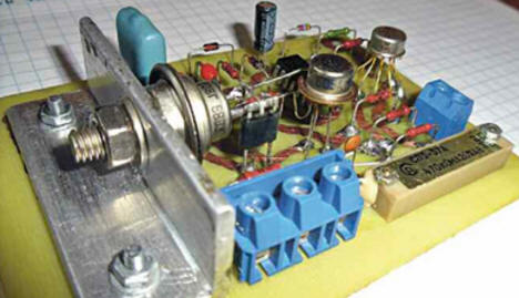
The appearance of the assembled device is shown in Fig. 2. Since the elements installed on its board are connected to a network with a life-threatening voltage of 220 V, electrical safety measures should be observed when setting up and operating the thermostat. The board must be placed in a housing made of dielectric material, the trimmer knob must also be insulated. Before switching on the device for the first time, check the correctness and quality of installation. Establishing a thermostat comes down to setting temperature control limits by selecting resistors R1 and R2. With the values indicated in the diagram, these limits are very wide, so it is advisable to either use a precision multi-turn tuning resistor (for example, SP1-3a) as R37, or narrow the limits to what is necessary for a particular application of the regulator. So, if it is required to maintain the temperature in the cellar in the range of 2.4 ° C, the resistor R1 can have a resistance of 220 kOhm, and R2 - 240 kOhm. In the case of using the thermistor RK1 as a remote temperature sensor, it should be taken into account that it is electrically connected to the mains. It must be protected from accidental contact by placing it, for example, in a housing made of insulating material. The remote thermistor is connected to the device board with a twisted pair of wires, the length of which should not exceed one or two meters. Do not immerse the thermistor in liquid. An exception to this rule can only be made with reliable waterproofing of the thermistor itself and the wires suitable for it.
The considered thermostat can be used to control the compressor of the refrigerator, if you make changes to its circuit, shown in Fig. 3. Since the compressor, unlike the heater, must be turned on when the temperature in the refrigerating chamber is higher than the set one, and turned off when it is lower, the inverting and non-inverting inputs of the op-amp DA1 are reversed. A positive feedback is introduced through the resistor R12, which creates the hysteresis necessary to prevent the compressor from turning on and off too often. If desired, the width of the hysteresis zone can be changed by selecting the resistor R12.
Since the refrigerator compressor is an inductive load, it is recommended to improve the reliability of its control, as shown in Fig. 4, connect in parallel with the triac VS1 RC circuit. Author: K. Gavrilov
Machine for thinning flowers in gardens
02.05.2024 Advanced Infrared Microscope
02.05.2024 Air trap for insects
01.05.2024
▪ Smartphone Microsoft Lumia 430 ▪ Powder coating of electrodes will improve battery parameters ▪ Why was the wheel invented so late ▪ Integration of smoke detectors into computers and mobile devices ▪ Huawei Ascend P1 is the thinnest smartphone
▪ site section Acoustic systems. Article selection ▪ article High-speed cord model 1,5 cubic meters. Tips for a modeller ▪ article How Many Magi Came to Worship Jesus? Detailed answer ▪ article Austrian black pine. Legends, cultivation, methods of application ▪ SIM Reader article. Encyclopedia of radio electronics and electrical engineering
Home page | Library | Articles | Website map | Site Reviews
www.diagram.com.ua |


 Leave your comment on this article: