|
|


 Arabic
 Bengali
 Chinese
 English
 French
 German
 Hebrew
 Hindi
Hindi Italian
 Japanese
 Korean
 Malay
Malay Polish
 Portuguese
 Spanish
 Turkish
 Ukrainian
 Vietnamese
|
ENCYCLOPEDIA OF RADIO ELECTRONICS AND ELECTRICAL ENGINEERING Relay IR control unit. Encyclopedia of radio electronics and electrical engineering
Encyclopedia of radio electronics and electrical engineering / Clocks, timers, relays, load switches According to IR commands given by any remote control from household appliances operating under the common NEC protocol (or similar), the proposed unit controls ten electromagnetic relays installed in it, which, in turn, can turn on and off various electrical appliances. It is possible to programmatically set the correspondence between the pressed buttons of the used remote control and the relays that change states on these pressings. Since ten relays are installed in the block, in the author's version, the digital buttons on the remote control "0" - "9" are selected to control them. When such a button is pressed, the relay corresponding to it closes its contacts, when pressed again, it opens them, when pressed again, it closes again, and so on. If you press the "VOL-" button, the contacts of all relays will open, and on the "EQ" button they will close. LEDs are provided to control the state of the relay. When all the relays have been activated, the unit consumes a current of 15...17 mA from a 24...200 V AC (or 250 V DC) source. This value depends on the applied relays. For the manufacture and adjustment of this unit, there is no need to know in advance the codes of commands given by the remote control used when pressing its buttons. You just need to make sure that the remote control works according to the protocol that matches NEC in terms of the encoding of the transmitted information and its volume (each command is four bytes). Please note that remote controls from different devices, even those operating on the same protocol, when you press functionally identical buttons, usually generate commands with different codes. To determine these codes, I developed a special program PriemNEC_Eeprom, which must be loaded into the microcontroller of the assembled device and, after performing simple operations, transfer the received codes to the working program of the microcontroller.
The diagram of the IR control block is shown in fig. 1. It does not contain unusual technical solutions, as well as scarce and too expensive parts. The commands sent using the remote control are received by the IR receiver module U1, the signals of which are fed to the input PD3 of the microcontroller DD1. The supply voltage of the microcontroller (5 V) was obtained from a voltage of about 1 V rectified by the diode bridge VD24 using an integrated stabilizer DA1. It is impossible to replace the imported 7805 stabilizer here with domestic KR142EN5A or KR142EN5V, since their permissible input voltage is only 15 V (unlike 35 V for 7805). Chips DD2 and DD3 - sets of electronic keys on composite transistors (maximum switching current 130 mA, voltage - 50 V). The K1-K10 relays are of the G2L-113P-V-US-24VDC type (winding resistance 1200 Ohm), the contacts of which are capable of switching current up to 5 A at alternating voltage up to 250 V.
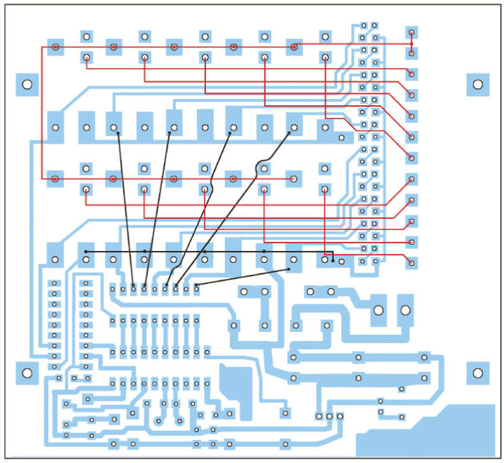
A board with dimensions of 120x110 mm, the drawing of printed conductors of which is shown in fig. 2 is made of textolite foiled on one side. The details on its opposite side of the printed conductors are located, as shown in fig. 3.
In addition to them, there are two jumpers made of bare wire. The dash-dotted line shows the contour of the plate heat sink of the stabilizer DA1. The height of the heat sink is 25 mm (according to the height of the relay). For the DD1 microcontroller, a panel must be provided on the board into which it is inserted already programmed. On the side of the printed conductors, the boards are mounted as shown in fig. 4, two groups of jumpers. Jumpers of one group are depicted with black lines. They are made from thin insulated wire. The red lines show the jumpers of another group, connecting the relay contacts in the required order with the XT1 terminal block. The cross section and insulation of the wire from which they are made must correspond to the current and voltage switched by the relay.
Before proceeding with the manufacture of the board, it is necessary to make sure that the remote control with which it is to be used works according to a protocol similar to NEC. To do this, you can use a simple node, assembled according to the scheme shown in Fig. 5 by connecting it to the microphone input of the computer's sound card.
The remote control is directed to the IR-sensitive window of the U1 module and, using the "Sound Recorder" program included in the Windows package (or another similar one), the signals emitted by the remote control when its buttons are pressed are recorded in computer wav files. You can view the waveforms of the recorded signals, for example, by running the WAVE editor built into the NERO software package. An example of an oscillogram of the NEC protocol console signal is available in the article [1]. The only difference is that the recording was made using a digital oscilloscope, not a computer. If the pulses and pauses between them in the signals of the studied remote control are the same as in the example, the duration and the total amount of information transmitted in each command (four bytes) are the same - the remote control is suitable for use with the described device. A detailed description of the various protocols used in IR remote control systems can be found in [2]. From there, the prototype of the program for decoding code packets was taken. Having assembled the described device, it is necessary, first of all, to determine which command codes correspond to the buttons pressed on the selected remote control. Most likely, they will differ from the remote control codes used by the author. To do this, load the codes from the PriemNEC_Eeprom.hex file into the program memory of the ATtiny2313-20PI microcontroller, install the microcontroller in the panel intended for it on the board, and turn on the power. Pointing the remote control at the IR receiver U1, press each of its buttons in turn at intervals of 2...3 s. Confirming each successful command reception, the HL1 LED on the board should flash briefly, and the HL3 state should change to the opposite. This is a sign that the code has been accepted and written to the EEPROM of the microcontroller. The maximum number of button presses that can be recorded in one launch of the program is 32. Their sequence must be remembered, or better, written down on paper.
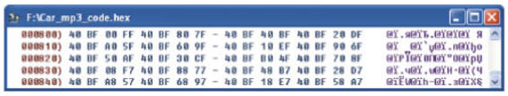
Next, the device should be turned off, transfer the microcontroller from its panel to the programmer panel, with which to read the contents of the EEPROM. On fig. 6 shows the window of the IC-Prog program with such content, obtained by the author in the study of the remote control he used from the car FM modulator. This remote control has 20 buttons and small dimensions (85x40x6mm).
Each pressed button corresponds to four consecutive byte cells. The codes in the first two of them (0x40, 0xBF) do not change from button to button, while the third and fourth contain the actual code of the command given by the button and its inversion. In the device under consideration, only codes from the fourth cells are used. On fig. 7 they are written to the right of the images of the remote control buttons from the FM modulator. You have to draw up a similar scheme for your own remote control.
It remains to make changes to the work program that adapt it to the existing remote control. To do this, using the AVRStudio program development environment, you need to open the Plata_IR_upravlenie_rele2.asm file and find the lines labeled one, mesg and Wataa in it. They are shown in the table, and for convenience, each of the mesg and Wataa arrays is divided here into several parts, provided with comments. The one constant contains the first two bytes of the command. As already mentioned, for all commands they are the same, but may vary from remote to remote. Those that your remote control transmits must be entered here instead of those in the program. The program does not analyze the third byte of the command, so its value is not required anywhere. The mesg byte array lists the codes (fourth bytes) of commands given to each of the used remote control buttons from the FM modulator. They should be replaced with the codes of the buttons of your remote control. Their maximum number is 15. Since only 12 buttons are used to control the relay, bytes from the thirteenth to the fifteenth are filled with non-existent button codes, instead of which, if desired, existing ones can be written, and these commands will be executed. The sixteenth byte contains the code 0xFF - a sign of the end of the array, it cannot be changed. An array of 16-bit Wataa words contains codes that determine the device's actions when receiving a particular command. The words in it follow the same order as the command codes in the mesg array. The first code (remote control button) corresponds to the first word, the second - the second and so on. The high byte of the word specifies the operation to be performed: 0x00 - turn off all relays, 0x01 - change the state of port B bits and related relays, 0x02 - change the state of port D bits and related relays, 0x03 - turn on all relays. Units in binary digits (one or more) of the low word mark those bits of the port indicated by the high byte, the state of which, when received by this command, should change to the opposite. Please note that the state of the PD3 and PD5 bits cannot be controlled in this way. The level at the pins of the PD0-PD2 bits will be changed by commands, but on the described board they are not connected anywhere. To use them, refinement is required. With high bytes equal to 0x00 or 0x03, the low byte is not parsed and can be anything. After making changes, the program must be assembled. As a result, a HEX-file of the working program adapted to the selected remote control will be obtained. Its contents should be loaded into the program (FLASH) memory of the microcontroller. If when you press the remote control button, the HL1 LED signaling the receipt of the command does not blink, you need to select the value of the Delay_1125us constant, which is responsible in the program for the exact formation of the time intervals necessary for correct reception. In the assembler file of the program, the .equ statement that assigns the value $B6 to it is at the very beginning of the "basic constants" section. In the AVRASM assembler, the $ sign and the 0x prefix are equal signs of a hexadecimal number. The constant should be chosen very carefully, changing its value by one. After each change, the program must be reassembled and the microcontroller reprogrammed. The microcontroller program can be downloaded from ftp://ftp.radio.ru/pub/2013/07/ir-upr.zip. Literature
Author: Yu. Svyatov
Machine for thinning flowers in gardens
02.05.2024 Advanced Infrared Microscope
02.05.2024 Air trap for insects
01.05.2024
▪ Full featured Thecus NAS 2U server ▪ New types of acoustic resonators for frequencies of 1,8...2,0 GHz
▪ section of the site Metal detectors. Article selection ▪ article Production of cinder blocks. Tips for the home master ▪ article What is a 17-year-old locust? Detailed answer ▪ article Operator of flour-grinding production. Standard instruction on labor protection ▪ article Motorcycle burglar alarm. Encyclopedia of radio electronics and electrical engineering
Home page | Library | Articles | Website map | Site Reviews
www.diagram.com.ua |


 Leave your comment on this article: