|
|


 Arabic
 Bengali
 Chinese
 English
 French
 German
 Hebrew
 Hindi
Hindi Italian
 Japanese
 Korean
 Malay
Malay Polish
 Portuguese
 Spanish
 Turkish
 Ukrainian
 Vietnamese
|
ENCYCLOPEDIA OF RADIO ELECTRONICS AND ELECTRICAL ENGINEERING Repair and modernization of household refrigerator. Encyclopedia of radio electronics and electrical engineering
Encyclopedia of radio electronics and electrical engineering / Clocks, timers, relays, load switches In the article, the author shares his experience in repairing a domestic refrigerator of the popular Indesit brand. Thanks to the replacement of a failed electromechanical relay with a specialized refrigeration equipment control controller, it was possible not only to fully restore the refrigerator's performance, but also to significantly improve its main technical characteristics. After seven years of operation, the Indesit SB167 two-chamber refrigerator, made in Lipetsk, stopped working. As expected, due to depressurization of the thermal sensor, the electromechanical thermal relay (Fig. 1), which controls the operation of the compressor, failed. This is a common malfunction of domestic refrigerators. The author repaired his first refrigerator with such a malfunction, while still a seventh grader. Contrary to expectations, this time it was not the movable corrugated “accordion” of the temperature sensor that was damaged, but its measuring tube: the manufacturer, when crimping and welding its tip, damaged the protective coating, presumably from a tin alloy, the copper part of the tube began to corrode until it lost tightness.
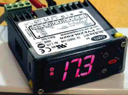
Initially, since the purchase of the refrigerator, it was noticed that the thermal relay in it did not work satisfactorily - most of the measuring tube was under the upper iron cover of the refrigerator, and a small part of it went into the closed evaporator chamber, so the temperature sensor reacted much more to the temperature in the room, and not in the refrigerator. In addition, the compressor on/off hysteresis was unnecessarily large. For these reasons, it was decided not to replace the damaged thermal relay with the same or similar one, but to use a modern electronic analogue instead, which has much greater accuracy and has a lot of additional functions. The choice fell on the electronic controller for the operation of refrigeration equipment model PJEZC00000K (Fig. 2). It performs the function of controlling the thermostat, and also allows you to control the operation of the fans and defrosting units of the refrigerator. The diagram of connection to the refrigeration equipment is shown on the label glued to its body (Fig. 3). The compressor (here it is indicated by an icon in the form of a circle with two non-parallel straight lines inside) is connected to terminal 5, the fan - to terminal 1, the heater - to terminal 3. The purpose of the remaining terminals is as follows: 4 - power input of the 230 V network, 6 and 7 - input step-down transformer power supply, 8 - input of the thermostat temperature sensor, 9 - "common" wire of the controller, 10 - input of the heater temperature sensor. There is a wide range of related models of such controllers, which differ in connection schemes and functionality (check them in the documentation attached to the controller).
On fig. 4 shows a simplified diagram of a refrigerator with an electronic controller installed in it (it is designated as module A1) instead of a thermal relay. The numbering of elements is conditional. Since the modernized refrigerator did not have equipment for forced ventilation and defrosting, the relay outputs for controlling the fan and heater are not used, and instead of the heater temperature sensor, a constant resistor R4 with a resistance of 10 kOhm is installed (in the absence of this resistor, the controller signals an error). The most vulnerable point in the applied controller is the step-down power transformer built into it, the mains winding of which is supplied with voltage without any protection elements. To reduce the likelihood of damage to this node, the mains voltage is applied to it through current-limiting resistors R2 and R3. The resistance of the primary winding of the transformer is 3,2 kOhm, the current consumed from the network in standby mode is about 7,6 mA at a mains voltage of 250 V and about 9 mA in the on state, the total voltage drop across these resistors is about 20 V.
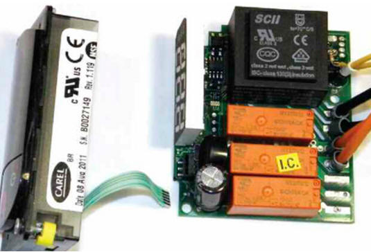
Since there was not enough free space in depth to place the controller (its case dimensions are 81x36x65 + 13 mm) in the niche of the plastic decorative front panel of the refrigerator, the contact terminals for screw connections were removed, the wires for connecting the device were soldered to the corresponding contacts of the printed tracks (Fig. 5; black wires - 230 V network, thin yellow wires - temperature sensor, orange - compressor switch-on relay). To securely fix the position, these wires were additionally glued to the printed circuit board with glue. In the photo at the top right, an additionally installed resistor R4 is also visible.
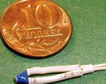
The controller manufacturer recommends using NTC thermistors with a resistance of 10 kΩ at 25 оC. In place of RK1, the author installed the first miniature thermistor with a negative TCR resistance that came to hand at 23 оWith about 10 kOhm (Fig. 6). Thin stranded mounting wires in insulation 200 mm long are soldered to its conclusions, the soldering points are insulated with heat-shrinkable tubes, a heat-shrinkable tube is also put on the thermistor body. It is not necessary to seal the temperature sensor. This temperature sensor was installed inside the refrigerator compartment in an inaccessible place that is not subject to frost formation and where there will be no melt water. In the modernized refrigerator, this place turned out to be the far lower part of the plastic cover for installing the backlight of the refrigerating chamber. The temperature sensor is glued with adhesive tape on its outer side, the attachment point is preliminarily degreased with alcohol. The temperature sensor is connected to the controller with a thin hard wire with double insulation, about 1,5 m long (used for mounting security systems, fire and other alarms). This wire passes into the refrigerator compartment through the existing backlight wire conduit. The manufacturer of the refrigerator was careless in sealing this hole, which was eliminated with the help of foam rubber. Also, a sheet of foam rubber 5 mm thick was placed under the top metal cover of the refrigerator. These simple measures made it possible to reduce the minimum achievable temperature inside the refrigerating chamber by 3...4 оWith continuous continuous operation of the compressor. Placing the temperature sensor inside the refrigerator compartment will allow the temperature sensor and the controller to measure exactly the temperature inside the refrigerator, and not something abstract, mostly room temperature, which was previously done by an electromechanical thermal relay.
The manufacturer guarantees at least 100000 operations for the electromagnetic relays installed in the controller. The two unused relays present in the device can, if necessary, be used to control the compressor instead of relays with worn contacts.
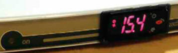
To install the controller, a rectangular hole was cut in the central part of the decorative panel of the refrigerator (Fig. 7). After checking the operation of the refrigerator, the installed controller is additionally fixed with a small amount of hot melt adhesive. The seam between its display and decorative panel is sealed to prevent leakage of detergent. Interfering parts of the bearing plastic mounting panel were cut off with an electric knife (in the central part this panel has no functional load). For additional connections, through which the mains current of 230 V flows, a stranded installation wire with a copper cross section of 0,5 mm is used2 in double PVC or rubber insulation (such wires were used in high-priced imported CRT TVs and other high-voltage equipment). Unfortunately, the manufacturer of the refrigerator used thin single insulation wire for installation. To increase electrical safety, it is recommended to put additional PVC tubes on these wires. The negligence of the manufacturer is also noticeable during the assembly of the refrigerator, for example, some fixing screws were missing. Resistors R2, R3 (see Fig. 4) are imported non-flammable or bursting, they are tightly fitted with insulating tubes 60 mm long made of dense fiberglass. The resistors are securely fixed in the place of the mounting panel where the electromechanical thermal relay was previously located. The type of LED HL1 installed by the manufacturer of the refrigerator and the resistance of the resistor R1 are unknown. Since the luminous display of the controller informs about the inclusion of the refrigerator in the network after the alteration, the indicated LED and current-limiting resistor can be excluded. Do not turn on the refrigerator in the "lying" position. After checking the performance of its components, the installed controller needs programming and may require calibration of the temperature sensor. Under normal operating conditions, the display shows the readings of the temperature sensor RK1. The power on of the compressor is signaled by the corresponding glowing icon on the LED display. If the error code "E0" is lit on it, then this means that the RK1 temperature sensor is out of order or not connected, and if "E", the resistor R4 is not connected. The blinking code "L0" or "H1" warns respectively about the emergency low or emergency high temperature in the chamber. To access all the parameters of the controller, hold down the "Set" button for more than 5 s. Pressing this button again - entry / storage. Buttons "Up", "Down" - parameter selection, value selection. To exit without saving, it is enough not to press any buttons for 60 seconds. To reset all user-set parameters to default values, press the "Down" and "Set" buttons simultaneously. The PJEZC00000K controller has many programmable parameters, but only a few of them are important for its use in a retrofit household refrigerator: * PS - password that must be entered to access all possible settings (default - 22); * C - calibration of the temperature sensor readings by reference thermometer. The author did not need to adjust this parameter, since the temperature values on the controller display and the readings of the control thermometers inside the refrigerator chamber coincided immediately. Control parameters start with the prefix "r": * rd - regulation differential (hysteresis). The default is 2, i.e. if the compressor cut-out temperature is set to +4 оC, then it will turn on at +6 оWITH; * r1 - lower limit of the set temperature. Allows you to set the minimum allowable set temperature, which will exclude the setting of an incorrect value; * r2 - upper limit of the set temperature. Allows you to set the maximum allowable set temperature, which will exclude the setting of an incorrect value. Compressor control parameters start with a "C" prefix: * C0 - start the compressor with a delay (in minutes) after restarting the microcontroller (default - 0, for a domestic refrigerator with a start-up relay on a thermistor, the delay can be set to 5...10 minutes, for old refrigerators with an electromagnetic start-up relay, you can leave the value at default); * C1 - minimum time between two starts in minutes (default - 0, it is desirable to set 5...10 min); * C3 - minimum compressor start time in minutes (default - 0, it is desirable to set 3...6 min); * SS - duration of a continuous cycle in hours (by default - 4 hours, you can leave this value). The defrost (begins with the prefix "P") and fan control (begins with the prefix "F") parameters are not used in the retrofit refrigerator. Alarm parameters start with "A" prefix: * AH - activation of the high temperature sound signal in degrees (when "AH" is equal to 0, the activation is disabled). Actual in the event of a malfunction due to depressurization of the cooling system, malfunction of the compressor or start-up relay; * Ad - temperature alarm delay. When a new controller is powered on for the first time, it must be set to a compressor cut-out temperature to activate it. To do this, hold down the "Set" button, wait for the set temperature readings, then use the "Up" and "Down" buttons to select the desired value and press "Set" again to save and exit. The first time a previously used controller is turned on, it is necessary to reset the microprocessor and then set the set compressor shutdown temperature. Functionally, the PJEZC00000K controller is almost identical to the PJ32C0000, as well as a number of other models, but they use a different connection scheme and a simplified display, which does not display icons for indicating the current operating mode. A complete list of all configurable parameters can be found in the instructions distributed on the Internet in the pdf files included with the controller documentation. You can buy a ready-made controller for controlling refrigeration equipment in stores selling industrial, commercial equipment or in online stores. It is convenient to use such controllers not only in domestic refrigerators, but also, for example, to control incubators, heating systems, heating, water heaters. When replacing thermistors with photoresistors, photodiodes, phototransistors, these controllers can control lighting. You can connect other sensors, for example, humidity, then the device will be able to control automatic watering or, for example, ventilation of basements, cellars. Author: A. Butov
Machine for thinning flowers in gardens
02.05.2024 Advanced Infrared Microscope
02.05.2024 Air trap for insects
01.05.2024
▪ Transistor of one molecule and several atoms ▪ Photon camera tracks endoscope in human body ▪ 200MP ISOCELL HP1 image sensor
▪ section of the site Children's scientific laboratory. Article selection ▪ article Pathological anatomy. Crib ▪ How is raisins made from grapes? Detailed answer ▪ article Basic principles of ensuring labor protection ▪ article Electronic ignition. Encyclopedia of radio electronics and electrical engineering
Home page | Library | Articles | Website map | Site Reviews
www.diagram.com.ua |


 Leave your comment on this article: