|
|


 Arabic
 Bengali
 Chinese
 English
 French
 German
 Hebrew
 Hindi
Hindi Italian
 Japanese
 Korean
 Malay
Malay Polish
 Portuguese
 Spanish
 Turkish
 Ukrainian
 Vietnamese
|
ENCYCLOPEDIA OF RADIO ELECTRONICS AND ELECTRICAL ENGINEERING Restoring the functionality of the Veritas sewing machine pedal. Encyclopedia of radio electronics and electrical engineering
Encyclopedia of radio electronics and electrical engineering / Consumer electronics In the Veritas sewing machine, to control the speed of the electric motor shaft, a carbon resistor connected in series with it and mounted in the pedal is used, the resistance of which decreases when the pedal is pressed. The resistor soon collapsed and it was not possible to find a replacement for it. I had to look for a regulator circuit capable of smoothly changing the rotational speed of an AC collector motor, starting from a starting voltage of 120 ... 140 V and ending with a full mains voltage of 220 V. Devices using the phase-pulse control principle turned out to be unsuitable due to unstable starting of the engine at low voltage .
It was decided to replace the carbon regulator in the pedal with a three-stage discrete one, assembled according to the scheme shown in fig. 1. Here M1 is the KN-4a AC collector motor installed in the Veritas sewing machine, SF1-SF3 are limit switches driven by a slider mechanically connected to the movable pressure part of the pedal, EL1-EL5 are miniature halogen lamps used in in this case as resistors. In the upper position of the pedal, the switches are in the state shown in the diagram and the motor M1 is de-energized. When you press the pedal, the contacts of the switch SF1 close first. As a result, EL1-EL3 lamps connected in parallel are switched on in the power supply circuit of the electric motor, and a starting voltage is supplied to it, causing its shaft to start rotating at a low frequency. When the pedal is pressed further, the SF2 switch is activated, the EL1, EL3 lamps are connected in parallel with the EL4-EL5 lamps, and the rotational speed of the electric motor increases, and after the SF3 switch is activated (in the lowest position of the pedal), the full mains voltage is applied to it, and the rotational speed increases to maximum, and all lamps go out.
Alteration of the pedal begins with the refinement of its base and moving part. To do this, first remove the axis connecting them into a single whole, and then all the parts installed on them. Next, on the milling machine, the protrusions 2-9 are carefully removed from the base (Fig. 2), and the protruding parts 1 and 10 are left untouched. In the movable part of the pedal, only the tongue located in its front part is refined (Fig. 3): its height is reduced with a file to 17 mm, and then a groove 4 mm wide and 15 mm long is made in it (first, a long drill is drilled - through the side wall - several holes, and then, using a needle file, give the groove the shape shown in the figure).
The device of the control mechanism for limit switches SF1-SF3 is shown in fig. 4. It consists of a slider 10 moving in the gap between the front planes of the limit switches 11-13 and guides 3, and a shaft 8 threaded through a groove in the tongue of the moving part of the pedal 7 and inserted into the holders 6, fixed with screws 9 through the pad 5 on the slider 10 (screws 4 are used for additional fastening of the lining to the slider). In the lower (according to the figure) part of the slider, a bevel is made at an angle of 45о. When you press the movable part of the pedal 7 in the direction shown by the arrow, its tongue presses on the slider 10, so it moves down and with its bevel "runs into" the limit switch button 13 (SF1). As a result, it works and turns on the EL1-EL3 lamps in the electric motor circuit of the machine. With further movement, the slider sequentially triggers switches 11 (SF2) and 12 (SF3). When the pressure on the pedal decreases, its movable part rises under the action of the return spring and pulls the roller 8 and the slider 10 connected to it upwards. As a result, the switches SF3, SF2 and SF1 successively return to their original position and the machine's electric motor is turned off. The pedal uses E53 CN-15A/250V limit switches used in microwave ovens. Two of them (13 - SF1 and 11 - SF2) are fixed with screws and nuts on the left wall of base 1 (SF1 - directly, SF2 - through tubular posts), and the third (12 - SF3) - on the right. Since the working travel of the pedal at the location of the switches is relatively small (approximately 22 mm), the distance between the buttons of the switches in height is chosen to be approximately 8 mm, for which they are installed differently (their relative position is shown on the right side of Fig. 4): SF1 is installed button up, and SF2 and SF3 - button down.
Slider 10 (Fig. 5) and pad 5 (it reduces the possible skew of the slider when moving up and down) are made of getinax 4 mm thick, guides 3 are made of textolite of the same thickness. The height of the lining is the same as that of the slider (25 mm), and the width is 0,5...1 mm less than the distance between the guides 3 at the bottom of the pedal base 1. M3 screws were used to fasten the lining to the slider, for which holes with a diameter of 3,2 mm, the centers of which coincide with the centers of the threaded holes in the slider. Holders 6 (Fig. 6) are made of a brass clamp of a PEV-R wire resistor. One end of the workpiece, approximately 21 mm long, is bent in the form of a ring with an inner diameter of 4 mm, and a hole for the M3 screw is drilled in the other. The roller 8 is made of a steel bar with a diameter of 4 mm. It is inserted into the holders 6 and the groove in the tongue of the movable part of the pedal during final assembly.
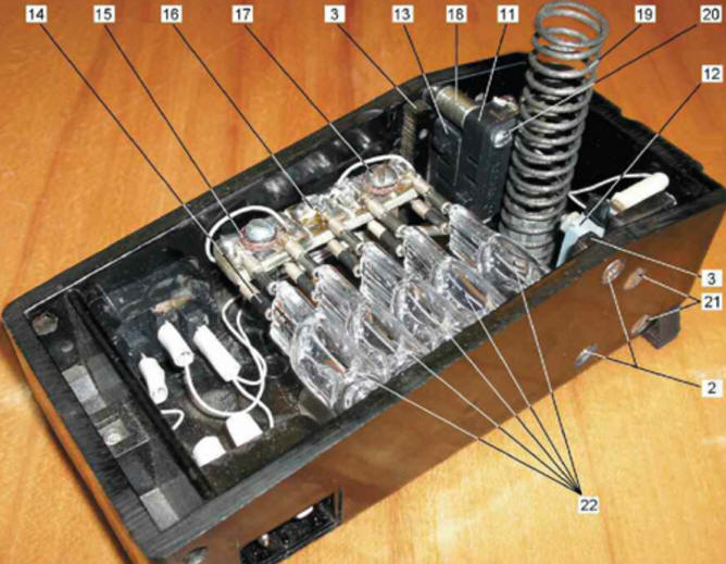
Lamps EL1-EL5 - miniature halogen "Navigator" NH JCD-230V-50W with a G6.35 base (the number 6,35 indicates the distance between the pins in millimeters). To connect them, a self-made socket was used (Fig. 7), consisting of a block 16 and five pairs of sockets 14 soldered to it.
The block is a package of three sheets of one-sided foil fiberglass 45x10 and 1,5 mm thick glued with epoxy adhesive (the foil is removed from the middle plate, and the outer ones are turned outward). After the adhesive has hardened, the remaining positions in fig. 7 are as follows: 18 - tubular support for fastening the SF2 circuit breaker; 19 - pedal return spring; 20 - screw for fastening the switch SF2; 21 - screws for fastening the SF3 circuit breaker. The power cords of the electric motor and the backlight of the sewing machine have not been altered. Connections of switches and sockets are made with MGTF 0,5 wire, which allows operation at elevated temperatures inside the pedal body (at a low speed of the electric motor). The three-socket socket shown in the photo, mounted on the left wall of the pedal base, was supposed to be used in one of the intermediate refinement options, it is not used in the final version. Author: A. Stepanov
Machine for thinning flowers in gardens
02.05.2024 Advanced Infrared Microscope
02.05.2024 Air trap for insects
01.05.2024
▪ Biodegradable olive pit material ▪ Nanomaterial for cleaning air on submarines ▪ AOC AGON PRO AG274QGM Gaming Monitor ▪ Wrist electronic gadgets are almost useless ▪ Wet tropics emit more carbon than they absorb
▪ site section Power Amplifiers. Article selection ▪ article So he wrote darkly and listlessly. Popular expression ▪ article Who ranks second after the US in agricultural export earnings? Detailed answer ▪ article Untying self-tightening knot. Tourist tips ▪ article Universal power supply. Encyclopedia of radio electronics and electrical engineering
Home page | Library | Articles | Website map | Site Reviews
www.diagram.com.ua |


 Leave your comment on this article: