|
|


 Arabic
 Bengali
 Chinese
 English
 French
 German
 Hebrew
 Hindi
Hindi Italian
 Japanese
 Korean
 Malay
Malay Polish
 Portuguese
 Spanish
 Turkish
 Ukrainian
 Vietnamese
|
ENCYCLOPEDIA OF RADIO ELECTRONICS AND ELECTRICAL ENGINEERING The BND-50/SG1 electronic timer is a universal heavy load control unit. Encyclopedia of radio electronics and electrical engineering
Encyclopedia of radio electronics and electrical engineering / Clocks, timers, relays, load switches The BND-50/SG1 digital electronic timer has 8 different programs and a built-in autonomous power supply. Given the low cost (200 rubles), many are happy to use this multifunctional device in everyday life. However, not everyone knows that the timer can be used not only for its intended purpose. New applications and features are discussed in this article. The appearance of the BND-50/SG1 digital timer is shown in fig. one. At the top of the timer housing there is a red LED that indicates the on state of the load. If we unscrew the two screws on the back of the timer case, we will get access to the electronic "stuffing" of the device, it is shown in fig. 2. The timer has a built-in disk Ni-Mh battery with a nominal voltage of 1,2 V and an energy capacity of 70 mAh. Thanks to him, the electronic circuit continues the countdown even when there is a power outage (the voltage in the 220 V network disappears). The elements of the device are mounted on two printed circuit boards, which are connected to each other using a 5-pin connector (designation on the board S1).
Rice. 1. Appearance of digital timer BND-50/SG1 Board 1 - electronic actuator (Fig. 2). It contains an electromagnetic relay, a 5-pin connector S1, a built-in battery, a rectifier and a voltage regulator (made according to a transformerless circuit), limiting resistors, smoothing capacitors and a bipolar transistor current amplifier. Board 2 (counting and programming unit) is shown in fig. 3.
Rice. 2. View of the internal filling of the digital timer On the board there is a timer chip (in a molded drop-shaped case) with electrical elements, and a mating part of the pin connector connecting the two boards of the device.
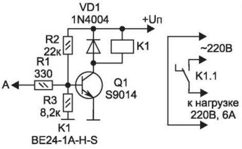
Rice. 3. Printed circuit board of the timing and programming unit The actuator board with a 5-pin connector is of particular importance in this device. This electronic unit can work as an independent executive device under the control of another electronic device (more on this below). Measurements of DC voltages between the contacts of connector S1 (contacts are counted from the designation S1): 1-2 - 100V 4-2 - 100V 4-3 - 3 V (4 - common, 3 - "+" power supply) 4-5 - 0,2V If the digital timer is connected to the network (before a certain programming mode is set), the load device will immediately turn on (and the indicator LED will light up). To turn off the load, it is necessary to close pins 4 and 5 of the connector, that is, apply a "zero" potential (relative to the common wire - pin 4 of connector S1) to pin 5 of the same connector. On fig. 4 shows the control circuit of the executive device (board 1). The executive unit is designed so that (in a device connected to a 220 V network) the current amplifier on the transistor VT1 is open, and the relay K1 is turned on. Relay contacts K1 close the electrical circuit of the load.
Rice. 4. Scheme of the executive unit of the electronic digital timer When a potential close to "5" arrives at point A (pin 1 of connector S0 - designation on the board), transistor VT1 closes, relay K1 and the load are de-energized. It is easy to convert this industrial device into an electronic control unit for a powerful load, where the control electronic unit connected to the actuator can serve not only a programmable digital (or mechanical) timer, but also, for example, a receiver of IR pulses or radio signals - that is, any electronic assembly with an output voltage of 2,5 ... 5 V DC. Timer Specifications and Selection of Components Maximum switching load 3,52 kW, 16 A in the lighting network 220 V, 50.60 Hz. The device uses a rectifier diode bridge DB107. The current amplifier is implemented on the popular bipolar transistor S9014 or analogues: S9015, S9018. The executive relay K1 is electromagnetic, designed for a constant voltage of 24 V (in the active state, the consumption current is 25 mA) and the switching current in the electrical circuit is 220 V up to 16 A. Author: A.Kashkarov
Machine for thinning flowers in gardens
02.05.2024 Advanced Infrared Microscope
02.05.2024 Air trap for insects
01.05.2024
▪ Artificial intelligence controls the tanker ▪ 15000 RPM Enterprise Hard Drives from HGST ▪ Fast walking can help you live longer ▪ Microchips 3D TLC NAND 32 GB
▪ section of the site Car. Article selection ▪ article Young everywhere is dear to us. Popular expression ▪ article What did Elon Musk originally want to name the Tesla Model 3 car? Detailed answer ▪ article Electrician of linear communication facilities. Standard instruction on labor protection
Home page | Library | Articles | Website map | Site Reviews
www.diagram.com.ua |


 Leave your comment on this article: