|
|
ENCYCLOPEDIA OF RADIO ELECTRONICS AND ELECTRICAL ENGINEERING Multiband speaker systems. Encyclopedia of radio electronics and electrical engineering
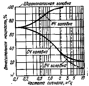
Encyclopedia of radio electronics and electrical engineering / Speakers The high demands placed on modern loudspeakers can only be met with multi-way loudspeaker systems with two, three or more drivers, each of which reproduces only a corresponding part of the spectrum of the wideband signal fed to the loudspeaker. Depending on the number of playback bands, acoustic systems can be two-, three-way, etc. The most widespread in amateur practice are two- and three-way acoustic systems. Loudspeakers with a large number of bands are used by professionals. Crossover filters are an integral part of any multi-band speaker system, ensuring that only those signal frequencies are fed to each dynamic head, for which it is intended to be reproduced. The total number of filters is equal to the number of heads. Depending on the frequency band for which the head is intended to be reproduced, there are low-, medium- and high-frequency dynamic heads. Recommended cutoff frequencies of crossover filters are 500 Hz, 1, 2, 3, 4, 8 kHz. The choice of values for the cutoff frequencies of the band separation depends on the frequency properties of the dynamic heads and the values of their nominal power. On fig. 1 shows the power curves of low-, medium- and high-frequency heads depending on the cutoff frequency of the band separation in relation to the power of a wideband head capable of reproducing power equal to the output power of the VLF, for which the multiband acoustic system is intended to work together. The dashed line indicates the power of the high-frequency head of the three-way system.
As can be seen from fig. 1, at a high separation frequency (2-4 kHz), the power of the low-frequency head should be equal to that of the wide-band head, while the power of the high-frequency head of a two-way system and the mid-frequency three-way system can be only 25 to 15%. At a low crossover frequency, the power of the low and medium frequency (or high) heads should be 82 and 60% of the power of the wideband head, respectively. Theoretically, in relation to standard sound programs, the power of medium and high frequency heads could be reduced by 1,5-2 times compared to the data in Fig. 1. But this should not be done, since it is necessary to have a reserve of the rated power of the heads in case of ULF operation with overload or its self-excitation. If this is not done, then high- and mid-frequency heads may fail. XNUMX-band crossover filters On fig. Figure 2 shows the schematic diagrams of the simplest separation single-link (a) and double-link (b) filters, and also gives their amplitude-frequency characteristic with an octave change in the signal frequency (c). Single-stage filters contain one capacitor and an inductor each, providing a slope of attenuation beyond the crossover frequency of 6 dB / oct, i.e. for each doubling of the signal frequency relative to the crossover frequency, the signal is attenuated by 6 dB (4 times in power).
Two-stage filters contain two capacitors and two inductors of different ratings, as shown in fig. 2b. They are more complex than single-link, but provide twice the steepness of the attenuation characteristic beyond the -12 dB/oct crossover frequency. The difference in the characteristics of these filters can be seen in Fig. 2, in. Depending on the nominal values of the resistances of the dynamic heads R, the band separation frequency F, the capacitances of the capacitors C and the inductances of the coils L can be determined by the known formulas:
where C is the capacitance of the capacitor, F; L-inductance of the coil, H; F-band separation frequency, Hz; R-resistance of the voice coil of the head, Ohm. When calculating the parameters of the elements of single-section separation filters according to the scheme of fig. 2,a it is convenient to use the data of the nomogram shown in Fig. 3a, which shows the dependences of the inductances of the coils and capacitances of capacitors on the frequency of separation of the bands and the resistance of the voice coils of dynamic heads (4, V and 16 Ohm). If the dimensions of the coil frame and the amount of winding are known, the number of turns can be calculated using a formula that takes into account the dimensions shown in Fig. 3b:
where n is the number of turns of the winding; Z-inductance of the coil, H; d is the average diameter of the coil, cm; b-winding width, cm; c is the average thickness of the winding, cm. The data in Fig. 3, a, b can also be used in the calculation of separation filters with two links (see Fig. 2, b). In this case, the capacitance of the capacitors decreases, and the inductance increases by 2 times, which will lead to an increase in the number of turns of the winding by 1,4 times. When manufacturing separation filter elements, the following should be borne in mind. Capacitors must be non-polar, i.e., non-electrolytic. These can be paper, metal-paper or ceramic capacitors. If there is no capacitor of the required capacitance, then it can be made up of several capacitors of a smaller capacitance, choosing their number so that the total capacitance is equal to the required value. It is recommended to use capacitors with a capacitance variation of no more than ±10% of the nominal value.
The winding of the inductors should be carried out with the thickest possible wire of the PEV-2 brand, so that the active loss of signal power in the separation filters is minimal. On average, winding is carried out with a wire with a diameter of 0,5 to 1 mm, and the greater the input power, the thicker the wire should be. This is a big disadvantage of multiband acoustic systems - in bulky crossover filters, from 10 to 25% of the power supplied to the loudspeaker is lost. In this regard, electroacoustic systems with multiband ULF have clear advantages. Dual band filter for... single head Let the reader not think that a typo has been made. Everything is correct. This is an adjustable filter designed to emphasize the low and high frequencies in a loudspeaker containing only one dynamic head.
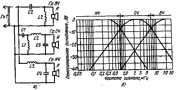
Its schematic diagram is shown in fig. 4, a, the amplitude-frequency characteristic - in fig. 4b. Using a variable resistor R1, you can adjust the attenuation of the signal at an average frequency of about 1 kHz to a level of -16 dB relative to frequencies of 0,1 and 10 kHz. The principle of operation of the filter is based on the use of a series resonant circuit consisting of a 1 mH inductor L1 and two series-connected electrolytic capacitors C1 and C2 of 50 microfarads each. The counter-connection of capacitors makes it possible to use two electrolytic capacitors as one non-polar one. The variable resistor shunts the resonant circuit, thereby affecting the frequency response of the filter as a whole. An adjustable filter connected between a loudspeaker with a single Gr1 wideband head with an impedance of 8 ohms and ULF contributes to a significant improvement in the sound quality of the loudspeaker when operating at a low level of input power. The filter, as it were, takes into account the physiological feature of the human ear to reduce its sensitivity at low and high frequencies compared to the middle ones as the sound volume decreases. Obviously, the filter according to the scheme of Fig. 4, and the most suitable for simple electro-acoustic devices that do not have effective volume and tone controls. Three-band crossover filters The schematic diagram of the simplest three-band two-section crossover filter and its amplitude-frequency characteristic are shown in fig. 5, a and b. The crossover frequencies are respectively 750 Hz (between the lower and middle) and 7 kHz (between the middle and upper). The steepness of the recessions of the amplitude-frequency characteristics outside the bandwidth -12 dB / oct. Depending on the choice of capacitor capacities and coil inductances, the filter can work with low-, medium- and high-frequency heads having a voice coil resistance of 4, 8 and 16 ohms. In this case, only heads with the same resistance can be used in one installation.
In the manufacture of a three-band crossover filter according to the scheme of Fig. 5, and data on inductors and capacitors are taken from Table. 1. When selecting capacitors and manufacturing coils, one should be guided by the recommendations given in the description of two-band crossover filters, and also use the nomogram and drawing shown in fig. 3, a, b. As amateur radio practice shows, the use of two- and three-way speaker systems equipped with the simplest crossover filters significantly improves the sound quality compared to loudspeakers using only one wideband head. At the same time, the fullest use of the capabilities of multiband systems requires special acoustic design of the heads and correction of their characteristics. Table 1
Literature
Publication: N. Bolshakov, rf.atnn.ru
Artificial leather for touch emulation
15.04.2024 Petgugu Global cat litter
15.04.2024 The attractiveness of caring men
14.04.2024
▪ New record in the field of high-temperature superconductivity ▪ Recreated volcanic lightning ▪ Editing of human embryos for the first time ▪ Chips based on 14nm technology 2 generations
▪ section of the site Application of microcircuits. Article selection ▪ article Superdeep well drilling. History of invention and production ▪ article When did the first instruments appear? Detailed answer ▪ article Fragrant Iowan. Legends, cultivation, methods of application ▪ article Consumer electronics. Power regulators, thermometers, heat stabilizers. Directory ▪ article Live electricity. Encyclopedia of radio electronics and electrical engineering
Home page | Library | Articles | Website map | Site Reviews www.diagram.com.ua | |||||||||||||||||||||||||


 Arabic
 Bengali
 Chinese
 English
 French
 German
 Hebrew
 Hindi
Hindi Italian
 Japanese
 Korean
 Malay
Malay Polish
 Portuguese
 Spanish
 Turkish
 Ukrainian
 Vietnamese


 Leave your comment on this article: