|
|


 Arabic
 Bengali
 Chinese
 English
 French
 German
 Hebrew
 Hindi
Hindi Italian
 Japanese
 Korean
 Malay
Malay Polish
 Portuguese
 Spanish
 Turkish
 Ukrainian
 Vietnamese
|
ENCYCLOPEDIA OF RADIO ELECTRONICS AND ELECTRICAL ENGINEERING
LED flashlight and its refinement. Encyclopedia of radio electronics and electrical engineering
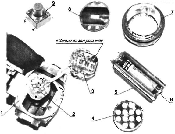
Encyclopedia of radio electronics and electrical engineering / electrician's tool Convenient Chinese LED headlamps can be purchased everywhere. In appearance, they are all very similar, and the difference is only in the number of LEDs and, accordingly, in cost. The insides of the flashlights are also almost the same: a cassette with batteries, two boards and a tact switch (without fixation) that controls the flashlight's operating modes. On a printed circuit board with a matrix of LEDs, there is a microassembly "flooded" with a drop of compound. Its internal circuit reacts to the closing of the contacts of the microswitch (at the end of the flashlight housing) in trigger mode. After the first press, 4 LEDs are lit, after the second - 8, after the third - all the LEDs (12 pieces). If pressed four times, then all LEDs flash at a frequency of about 2 Hz, and after the fifth press, all LEDs are off. The process is then repeated in a cyclical algorithm. The control pulse for the microassembly is negative, that is, the trigger is triggered by the negative edge of the input pulse (or when the power is shorted to "-"). This is not always convenient. More often, only two positions are required: all LEDs on or off. How to convert the flashlight into two modes at the lowest cost? Despite the similarity of headlamps, there are printed circuit boards with different track layouts and the number of LEDs, so there is not much point in giving a detailed diagram, because it is possible that the reader will not find exactly the same version of the flashlight anywhere else (but others may come across). For this reason, it makes no sense to modify the device by supplementing the logical circuitry using a new trigger that would have only two LED matrix control modes. Considering the above arguments, as well as the low cost of the flashlight itself and the lack of free space for the revision board (microcircuit), we had to abandon such an undertaking and proceed in a different way. The simplest recommendation for improving the device in terms of time, minimum parts and efficiency is to replace the standard SDTM-630-M non-latching mode switch (others may also be found) with an almost similar in appearance, but with fixation: such as PS700L, PS645L, PS850L (cost 12-18 rubles), where the numbers in the designation indicate the size of the button (for example, PS700L - 7 mm). Next, consider the option of reworking a specific model of the Bailong ВL-536 portable headlamp with three AA batteries (LR6) and an SDТМ-630-N tact button, shown in the photo with 12 LEDs (for a different number of LEDs or a different type, you will need to make adjustments to the resistance of the limiting resistor, about it below). So, we disassemble the body of the flashlight and take out the battery pack. Having unscrewed two self-tapping screws with a Phillips screwdriver, we take out the board with the microswitch. We unsolder the standard switch (flexible leads in the holes of the board) and instead install a microswitch with fixing the position of the PS700L type. It has six contacts, two of them are "cut off" with wire cutters before being installed into the board in a regular place (with four holes). By the way, in this case, the button with fixation from the control panels of old (10-year-old) car radios is perfect in size. Next, you will need to make changes to the printed circuit board with the LED matrix (it is even easier to remove it from the flashlight body - through the hole in the glass lens). All LEDs must be connected in parallel to each other using flexible mounting jumper wires of the MGTF-0,6 type. The printed conductors leading to the microcircuit are cut off.
To break the simplest electrical circuit (4,5 V battery - latching microswitch - LED matrix), a constant resistor with a resistance of 24 Ohm ± 10% is included to limit the current in the circuit (directly applied voltage of 4,5 V to the LED matrix will cause a large and even an unacceptable current, which can lead to failure of the LEDs), and in this case it is not necessary to create a pulsed current stabilizer for the above arguments: the game is not worth the candle. The resistance of the limiting resistor is calculated according to Ohm's law so that the voltage drop across it is 2 ... case 2,5 mA). Well, of course, taking into account the above recommendations, it is necessary to "work" with the printed conductors on the LED matrix. Now this Chinese product works the way you like, without tiring "extra" three of the five modes, and its appearance has not changed. It would be nice if this article was read in the "Celestial Empire". Author: A.Kashkarov
Traffic noise delays the growth of chicks
06.05.2024 Wireless speaker Samsung Music Frame HW-LS60D
06.05.2024 A New Way to Control and Manipulate Optical Signals
05.05.2024
▪ Wind power will fully provide Brazil with electricity ▪ Ultra-thin and flexible electrophoretic display ▪ A relativistic jet with a strong magnetic field has been obtained ▪ The solar wind creates an electrical charge on Phobos ▪ Case for isolating the smartphone from the owner
▪ section of the site Life of remarkable physicists. Article selection ▪ article Stretch to the line. Popular expression ▪ article Why doesn't Spielberg come to shoot the last scenes of the films he directs? Detailed answer ▪ Article Florentine iris. Legends, cultivation, methods of application ▪ article Radiation indicator. Encyclopedia of radio electronics and electrical engineering
Home page | Library | Articles | Website map | Site Reviews
www.diagram.com.ua |

 Leave your comment on this article: