|
|


 Arabic
 Bengali
 Chinese
 English
 French
 German
 Hebrew
 Hindi
Hindi Italian
 Japanese
 Korean
 Malay
Malay Polish
 Portuguese
 Spanish
 Turkish
 Ukrainian
 Vietnamese
|
ENCYCLOPEDIA OF RADIO ELECTRONICS AND ELECTRICAL ENGINEERING Speaker protection device. Encyclopedia of radio electronics and electrical engineering
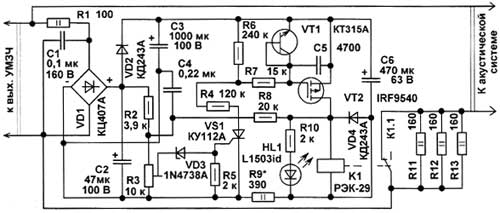
Encyclopedia of radio electronics and electrical engineering / Speakers In life, situations are not uncommon when, for one reason or another, speaker systems are connected to audio frequency amplifiers whose power exceeds the maximum allowable for the system, which, on the one hand, often allows you to get better sound quality, increase the dynamic range, on the other hand, increases the risk damage to dynamic heads due to overload. This is especially true when using speakers at school, student, youth parties, where acoustics are often connected to the first working amplifier that comes across, which is "more powerful". In order to prevent damage to the AU when power exceeding the rated power is supplied to it, it must be equipped with an overload protection unit built into the AU and not requiring an additional power source. A schematic diagram of such a device, designed to protect speakers with a power of 10 ... 35 W, is shown below.
In addition to shutting down the speaker in case of overload, this device also protects its dynamic heads from damage in the event of failure of the amplifier transistors and the appearance of a constant voltage at its output. The device is connected to the output of an audio frequency power amplifier. The AC voltage is rectified by the diode bridge VD1. Resistor R1 eliminates the influence of the device on the operation of the power amplifier. The rectified voltage is smoothed by oxide capacitors C3, C2. As long as the power at the output of the amplifier does not exceed the maximum allowable for the AC, the voltage at the terminals of the capacitor C2 is small, the zener diode VD3 is closed, therefore, the trinistor VS1 is also closed. In the microcurrent mode, SCRs of this type are controlled, i.e., they can be closed by removing the control voltage. Since VS1 is closed, transistor VT2 will also be closed. The contacts of the relay K1 are closed, 100% of the power will be supplied to the dynamic heads of the AC. As soon as the power at the output of the amplifier exceeds that allowed for the AC, the voltage at C2 will increase so much that the zener diode VD1 opens, the trinistor VS1 and the transistor VT2 open, the relay contacts K1 open, the power supplied to the AC will be limited by resistors R11-R13. These resistors act as a load on the power amplifier, which improves the stability of the amplifier in the event of a loudspeaker shutdown, in addition, these resistors reduce sparking between the relay contacts when they are closed and opened. When the overload protection is triggered, the HL1 LED lights up. Transistor VT1, the emitter junction of which operates as a micropower zener diode with a stabilization voltage of 7 ... 12 V, protects the field-effect transistor from breakdown of the gate insulator. As soon as the voltage at the output of the amplifier decreases, the zener diode VD3 will close, VS1, VT2 will close, the contacts of relay K1 will close, full power will again be supplied to the AC. Resistor R8 introduces a small hysteresis that prevents the relay contacts from cycling at a constant output power slightly above the threshold. Resistor R9 reduces the current through the relay winding when its contacts open, capacitor C6 accumulates enough energy necessary for reliable operation of the relay. When the structure is placed inside the speaker cabinet, the structural elements operate in conditions of sufficiently strong vibrations in a wide range of sound frequencies created by dynamic heads, in addition, in some cases, an alternating magnetic field from dynamic heads should be taken into account. The printed circuit board should be located at the maximum distance from the open magnetic systems of the dynamic heads. The device uses fixed resistors MLT, Cl-4, C2-23 or imported analogues. It is desirable to use the tuning resistor R3 in a closed case, for example, SP4-1, SPZ-16v, SP5-16A, SPZ-19a, SP4-3. After tuning, the rotary axis of the resistor should be fixed with a drop of paint. Capacitor C1 film polyethylene terephthalate K73-17, K73-9 or similar. C4 - ceramic K10-17, KM-5, oxide capacitors - K50-35 or imported analogues. Capacitor C3 can be made up of two 470 uF capacitors (this is provided on the printed circuit board). If necessary, capacitor C6 should also be used for an operating voltage of 100 V. In case the device is used with amplifiers that have a supply voltage of the output stages of more than ±50 V, oxide capacitors must be for a voltage of 160 V, the power and resistance of resistors R1, R2 , R9 also needs to be increased. Capacitors C3, C6 are installed parallel to the printed circuit board and additionally fixed to it with wire ties. The diode bridge can be replaced with a similar low-power one, for example, DB103-DB107, RB153-RB157, or made up of four rectifier diodes with an operating voltage of at least 100 V. Instead of KD243A, you can install any of the KD243, KD247, KD208, KD105, 1N4002-1N4007 series. The zener diode 1N4738A can be replaced with KS175A, KS175Zh, KS126K, LED - with any other. Instead of the trinistor KU112A, you can use KU 112 AM in the TO-92 package. Field-effect n-channel transistor IRF9540 in this design can work without a heat sink. Its maximum drain-source voltage is 100 V, the domestic analogue is KP785A. Instead of this transistor, you can use IRF9634, KP796A, having UCH MAX\u250e 315 V. Instead of KT312A, you can use any of the KT315, KT9014, SS1 series. Relay K29 - REK-4.501.56, passport DUSCH950. The winding resistance of this relay is about 15 ohms, stable switching of contacts occurs at a voltage of 7 V, the minimum holding voltage is XNUMX V. A relay of this type was used in the remote control modules of domestic USCT televisions. When replacing, you should take into account the fact that the contacts of this relay must switch a significant current.
The device can be mounted on a 140x50 mm printed circuit board, where all elements are installed, except for the LED. On pic.2 the printed circuit board is shown from the side of the conductors. On the mounting side, it is desirable to cover the board with three or four thin layers of epoxy glue. Each next layer is applied after the previous one has hardened. The board is attached to the AC case from the inside with five M3 screws or self-tapping screws. If possible, it is desirable to close it with a blank thick-walled (> 0,5 mm) casing, which will also reduce the likelihood of device failure due to vibrations in powerful speakers, as well as reduce the likelihood of relay contact bounce. Two copies of these devices made by the author are used in conjunction with 15AC-220 acoustic systems that use 25GDN-3-4 dynamic heads. These systems begin to wheeze and rattle at more than 40 watts of input power. The protection threshold is set to 25 W. These speakers are powered by the Orbita UM-002 stereo amplifier, which is capable of developing power above 50 W at a 4 ohm load. The other two copies are installed in self-made sealed speakers, assembled on 10GDSh-1 broadband heads, powered by a Corvette 50U-068 C amplifier. The threshold for switching on the protection is also set to 25 W based on the operation of the amplifier for a load of 4 ohms. If, when working with powerful speakers (> 35 ... 5O W) and a powerful amplifier, the trinistor closes at too low a power for this case, the resistance of resistors R4 and R7 can be doubled. This device can be modified by installing a thermistor with a negative TCR resistance of 2 ... 3,3 kOhm at 4,7 ° C instead of a constant resistor R25, which should be rigidly fixed through a gasket made of thermally conductive rubber on the magnetic system of a powerful low-frequency head. In this case, with a strong heating of the magnetic system, the device will turn on protection at a lower output power of the amplifier. Author: A. Butov, p. Kurba, Yaroslavl region; Publication: cxem.net
Artificial leather for touch emulation
15.04.2024 Petgugu Global cat litter
15.04.2024 The attractiveness of caring men
14.04.2024
▪ The ovary was printed on a 3D printer
▪ section of the site Stories from the life of radio amateurs. Selection of articles ▪ article Basic principles of geology. History and essence of scientific discovery ▪ article Which animals have the most genes? Detailed answer ▪ citrus article. Legends, cultivation, methods of application ▪ article Domestic coaxial cables. Encyclopedia of radio electronics and electrical engineering
Home page | Library | Articles | Website map | Site Reviews
www.diagram.com.ua |


 Leave your comment on this article: