|
|


 Arabic
 Bengali
 Chinese
 English
 French
 German
 Hebrew
 Hindi
Hindi Italian
 Japanese
 Korean
 Malay
Malay Polish
 Portuguese
 Spanish
 Turkish
 Ukrainian
 Vietnamese
|
ENCYCLOPEDIA OF RADIO ELECTRONICS AND ELECTRICAL ENGINEERING Acoustic system for self-production. Encyclopedia of radio electronics and electrical engineering
Encyclopedia of radio electronics and electrical engineering / Speakers Now on sale (at least in large cities) you can buy the most diverse in terms of power, design, overall dimensions and cost of acoustic systems for almost every taste, ranging from small volumes of 2...3 dm3 up to floor volumes over a cubic meter. However, the vast majority of these systems have one common feature: they are all of the compression type. This means that the loudspeaker case is tightly closed and the loudspeaker cone works like a piston, the cylinder of which has a constant volume of enclosed air inside. All compression systems have a number of indisputable advantages, among which the most important are the following: 1. The acoustic short circuit between the front and rear sides of the loudspeaker cone is completely eliminated, which increases the relative (but not absolute!) response at the lowest extreme frequencies and, therefore, reduces the overall frequency response unevenness due to this part of the spectrum.
However, as they say, only cheese in a mousetrap is free. Everything else has to be paid for. In the case of compression loudspeakers, the trade-off is their efficiency and, therefore, the electrical power that must be supplied to the system in order to obtain sufficient sound volume. Readers probably paid attention to the fact that most modern portable and compact receivers, radio tape recorders, as well as their car twins, have a passport output power of 50, 60, 100 and even 300 W! Meanwhile, the vast majority of old tube radios and radios, even of the highest class, had an output power 10 ... 20 times less. For example, the highest-class console stereo radio "Symphony" had an output power of each channel that did not exceed 6 W, first-class desktop receivers "Latvia", "Mir", "T-689" had an output power of 5 W, although the volume of their sound was by no means less , but rather more than today's car radio with a nameplate power of 2x30 watts. What's the matter? But the fact is that before the widespread use of transistor radio equipment, not compression, but exclusively open radiators were used as acoustic systems, i.e. those in which the rear side of the speaker cones communicated with the air volume of the room through the perforated back wall of the case. Although these open loudspeakers did not have the advantages of compression systems, they nevertheless provided excellent sound quality with much less electrical power input. A comparison of the two types of speaker systems is provided so that the radio amateur can make the right choice. The fact is that today's nomenclature of powerful terminal transistors makes it possible to obtain undistorted output power of 50 and 100 W with exceptionally high efficiency, since special circuit solutions allow these transistors to operate in class B with virtually no noticeable non-linear distortion. In this case, the use of compression acoustic systems is not only possible, but also quite justified. The situation is different with tube amplifiers. Modern tube end stages can only work in pure class A. This is necessary to ensure an acceptable level of non-linear distortion. But this, as you know, is the most uneconomical mode. In addition, powerful terminal lamps consume a large current through the filament circuit, so it turns out that even with an output power of 10 ... 15 W, the amplifier consumes more than 100 W from the network. It is clear that it is simply pointless to create a tube amplifier with an output power of 100 W or more for the normal buildup of a sufficiently powerful compression system: it will consume at least 1 kW from the network and, accordingly, generate heat on a par with an iron or electric stove. It follows that an open-type speaker system is preferable for a tube amplifier. But such systems today are not produced by almost any company either in Russia or abroad. What is left for the reader to do? It remains for him to build such a system himself. For those who have never done this, we inform you that it is not at all as simple as it may seem at first, and that building a high-quality loudspeaker system is no easier than building a high-quality amplifier. Therefore, we will give not only a detailed description of one of the systems (far from the most complex), but also accompany it with explanations and comments that will help you competently approach the choice of loudspeaker types, determine the shape and size of the case and structural materials for its manufacture. You should start designing an acoustic system by setting the basic parameters. The main indicators of any speaker system are: 1. Really reproducible frequency range for sound pressure.
These parameters are directly related to the choice of types and number of loudspeakers that can solve this problem. Here again a small digression into the field of theory is required, without which much of the further reasoning may turn out to be incomprehensible. Let's start by looking at how a loudspeaker works. For effective radiation of the lowest frequencies, the loudspeaker cone must have the maximum possible radiating surface (cone area), extremely soft suspension (elastic corrugation and low elasticity of the suspension), which entails a sufficiently large inertia of the entire system. However, at the lower frequencies of the range, this practically does not negatively affect the sound quality of bass instruments. To effectively reproduce the higher frequencies of the range (starting from 8 ... 10 kHz), the requirements for the loudspeaker are reversed. The diffuser can be small, but necessarily rigid: very often, to achieve this goal, a paper diffuser is impregnated with bakelite varnish, and for the most expensive models (mainly Western firms) they are made of plastic or light duralumin. The suspension of the coil is made rigid and as inertialess as possible. Even what has been said is enough to understand that one loudspeaker is indispensable for effective radiation of a wide spectrum of frequencies. Indeed, the vast majority of broadband speaker systems consist of three or more different drivers. Why three and not two? Because a good low-frequency loudspeaker with a low frequency of its own mechanical resonance effectively radiates only frequencies no higher than 4 ... 6 kHz, and high-frequency heads start working from 8 ...
In the author's version, this concept is expressed in the choice three standard industrial loudspeakers: 1. 6GD-2 RRZ - as the main low-frequency one (frequency band 40 ... 5000 Hz, natural resonance frequency 25 ... 35 Hz, rated power 8 W, impedance XNUMX Ohm). It was used in the top-class stereoradiol "Symphony".
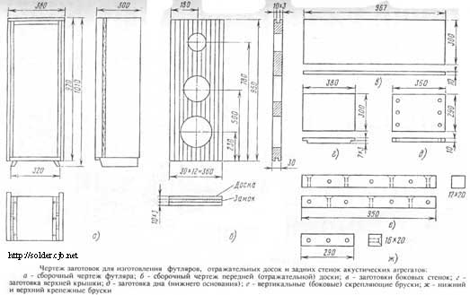
It is likely that it is impossible to purchase these particular loudspeakers today. There is nothing to worry about, since the types available for sale are not only not worse than those indicated, but often surpass them in basic indicators. It is important only when choosing them. Adhere to the given ratios of nominal powers (6:4:1) and, if possible, the ratios of impedances. It goes without saying that the power rating of replacement loudspeakers cannot be less than those recommended. Well, for those who do not intend to engage in independent calculations and design, we will give a detailed description of the simplest, but nevertheless quite meeting the requirements of Hi-Fi acoustic stereo system, consisting of two identical 10-watt speakers - providing sound with a large margin of room area up to 50 m and specially designed for the previously described stereo amplifier 2x8 (10) W. So let's start with the case. For its manufacture, you will need good, defect-free (preferably aviation) plywood 10 ... sheet rubber (you can use old car tubes), as well as 12 special shipping pads made of loose cardboard used in the packaging and transportation of chicken eggs, and good carpentry or casein glue. In addition, you will need special joinery and carpentry tools for woodworking (longitudinal sawing of a thick board, sawing plywood, planing, cutting holes for loudspeakers in the front board and perforations on the back walls), as well as wide clamps or clamps for making a glued front shield. The figures show drawings of individual parts of the case and its general view, indicating the main dimensions. As for the number, shape and size of the holes in the front shield, they will be determined solely by the overall dimensions of the loudspeakers used by the radio amateur and their number. The dimensions shown in the figure correspond to loudspeakers of the 6GD-2 RRZ (low-frequency), 4GD-7 (mid-frequency) and 1GD-3 RRZ (high-frequency) types. It should be noted that when using loudspeakers of any other types, their relative position and the coordinates of the centers on the front shield must be kept as indicated in the drawing. If two identical ones are used instead of one high-frequency loudspeaker, they must be placed side by side, horizontally and symmetrically with respect to the coordinates indicated on the drawing for 1GD-3. They must be connected to each other in series and in phase. Work should begin with the most difficult and time-consuming part of it - the manufacture of the front shield. This shield is assembled from individual spruce or pine bars, cut from a single, well-dried, unwarped board with a thickness of at least 30 mm (in planed form). The board is sawn lengthwise into separate bars with a section of 30x30 mm and a length of 1,1 m (with a technological margin). After carefully processing the bars with coarse sandpaper, they are glued with a board of the required width (with a small margin) using carpentry or casein glue, and, clamping it in clamps or clamps, leave it to dry for at least a week.
You can trim the case with valuable veneer (walnut, Karelian birch) or paste over with a self-adhesive film "wood-like". Exterior finishing must be completely finished before final assembly of the unit.
Now we need to make the back walls. They are cut from 4mm plywood exactly to the size of the back "window" of the case. Then you need to take three shipping tablets from the eggs and put them on the table with the "loose" side of the cardboard down. With a sharp knife or hacksaw blade, you need to cut flush all the "smooth" cones protruding from above, then put all three tablets with the cut side on the back wall and mark future holes in the back wall through the holes formed in the tablet with a pencil. After all the marked holes are cut out in the plywood, the back wall must be painted with a stain or other water-soluble paint, gauze is glued on the inside over the entire area and, after it has completely dried, the prepared plates are glued on top of the gauze, making sure that the holes in them are precisely positioned against the holes in the back wall. On this, you can consider the manufacture of the rear walls finished and return to the front panel. If the front panel is well dried and the glue "tightly" connected the individual bars into a whole board, you need to carefully and with a high degree of accuracy cut it to the desired size. Such a size is considered necessary so that after sticking sealing rubber strips-belts on all four end sides of the board, the board fits tightly and without gaps inside the case from the front side. Fastening the board to the case can be solved in different ways. In the author's designs, mounting brackets-angles with washers and "lambs" from mounting the kinescope to the TV case were used.
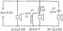
When the front board fits exactly to the opening of the case and is glued on the ends with rubber strips, you can start cutting holes for the speakers. In this case, it should be taken into account that the diameter of the hole in the board, to the nearest millimeter, must correspond to the distance between the inner edges of the cardboard sticker on the loudspeaker from the diffuser side. After cutting all the holes, the inner end sides of the holes must be carefully sanded with sandpaper, wiped from the resulting dust and covered with any varnish or nitro paint. Now, on the outer side of the board, you need to stick or stretch radio fabric or any other, but always rare (transparent) matter with the help of small carnations. Only then can loudspeakers be installed on the front panel, while ensuring their absolutely precise centering relative to the holes in the board. The remaining six "egg" tablets (for each of the cases) must be nailed or glued to the inner sides of the side walls of the case (three for each wall) with a "loose" layer of cardboard inside the case. This makes it possible to almost completely eliminate reflections from the side and rear walls of the case and significantly reduce peaks and dips in the frequency response of the unit in terms of sound pressure. The loudspeakers are connected to each other in accordance with the diagram shown in fig.
The parameters of the parts indicated in this diagram correspond to the types of loudspeakers used. Consider the phasing of the loudspeakers inside the speakers and the speakers among themselves. This is an extremely important matter, because with incorrect phasing, even a perfectly assembled system will work very badly. Unfortunately, many radio amateurs do not know this or do not attach importance to this, paying for the poor performance of good speakers. The physical meaning of phasing is that in a group of parallel, series or mixed-connected loudspeakers operating from a common two-wire line, when a DC voltage of positive or negative polarity is applied to the input of the line, the diffusers of all loudspeakers react in the same way: either they are drawn into the magnetic gap, or they are pushed out of him. It is unacceptable for the cones of different loudspeakers to move in opposite directions. In practice, things are a little more complicated. The fact is that the high-frequency loudspeaker is connected to the line through an isolation capacitor, and the mid-frequency one is shunted by a choke, so when a battery (1,5 V) is connected to the line, you can simply not notice the diffuser deviation. So for the time of checking the common mode, the isolation capacitor must be short-circuited with a jumper, and the inductor must be unsoldered on one side (any). To change the phasing of any loudspeaker, you need to swap the wires suitable for it, and after finishing work, do not forget to restore the temporarily broken circuit. After all the loudspeakers inside each of the speakers are in phase, the speakers should be phased with each other. To do this, both speakers must be placed close to each other at a distance of 2 ... 3 m from the operator "facing" to him, turned on in parallel and a signal from a sound generator with a frequency of 200 Hz of a very low level should be given, so that the sound was barely audible . One wire from one of the speakers (any) must be broken and a long piece of connecting wire must be included in the resulting gap so that the operator, being at a distance of 3 m from the speakers, can alternately close and open the broken circuit. If, when the broken circuit is closed, the volume hardly changes or increases very slightly, then the speakers are phased correctly. If, when connecting a second, open speaker, the sound volume decreases sharply or the sound ceases to be heard at all, then the speakers are turned on in antiphase. In this case, the wires from one of them (it doesn’t matter which one) must be swapped and once again make sure that the speakers work in phase. After that, the same-named ends of the wires of both speakers must be marked (painted over with paint, wrapped with electrical tape, put on a vinyl chloride “stocking”), so that later they can be properly soldered to connectors or other connectors that exclude non-phase connection of two speakers to the outputs of stereo amplifier channels. It is useful to check for common mode again with the working amplifier, since it may turn out that the secondary windings of the output transformers in the two channels of the amplifier have different phases at the output. With such a test, a signal with a frequency of 200 Hz from the generator must be simultaneously applied to both inputs of the amplifier. And finally, a final note about columns. Since the current at peak power (10 ... 12 W) exceeds 3 A, the connecting wires must have a sufficient cross section so that there is no noticeable signal voltage drop on them with a length of 3 ... 5 m. It is best to use a standard lighting cord from household electrical appliances as connecting wires for speakers. The wires must be solid, connections in them are unacceptable. Before using the speakers, you need to check each of them for the absence of rattling. To do this, a sound generator is connected to the input of the amplifier, the signal level is set to correspond to the nominal power of the speaker (in our case, 10 W) and the frequency is changed very slowly within the entire band, from 40 Hz to 18 kHz, maintaining the output power unchanged and carefully listening to the appearance extraneous overtones and rattles. Most often, they are caused by loose washers under screws and screws, a loosely screwed back wall, sound-absorbing plates that are not securely glued, radio fabric or shavings that are loosely stretched on the front panel, sawdust and small foreign objects caught between the diffuser and radio fabric. All identified causes must be eliminated before the start of operation of the complex. And if you were not too lazy and did everything that was recommended, the author guarantees you great sounding that the owners of 50 and 100-watt compression speakers will envy. Author: tolik777 (aka Viper); Publication: cxem.net
Artificial leather for touch emulation
15.04.2024 Petgugu Global cat litter
15.04.2024 The attractiveness of caring men
14.04.2024
▪ Artificial intelligence recognizes silent speech ▪ Meizu Smart Button to Control Home Appliances ▪ Pregnancy and childbirth changes a woman's brain ▪ The earth is pushing the moon faster
▪ section of the site Data transfer. Article selection ▪ article Electric boiler. Tips for the home master ▪ article Drill with heat sink. home workshop ▪ article TECSUN receiver upgrade. Encyclopedia of radio electronics and electrical engineering
Home page | Library | Articles | Website map | Site Reviews
www.diagram.com.ua |


 Leave your comment on this article: