|
|


 Arabic
 Bengali
 Chinese
 English
 French
 German
 Hebrew
 Hindi
Hindi Italian
 Japanese
 Korean
 Malay
Malay Polish
 Portuguese
 Spanish
 Turkish
 Ukrainian
 Vietnamese
|
ENCYCLOPEDIA OF RADIO ELECTRONICS AND ELECTRICAL ENGINEERING Tuning the system unit of the computer. Encyclopedia of radio electronics and electrical engineering
Encyclopedia of radio electronics and electrical engineering / Computers Something is missing I was prompted to write the article by the questions of users who, one way or another, want to change the appearance of the system unit. Here we will talk about what you can do with this box, as well as what you should not do with this box. So, chisel and hammer in hand - let's start! Warning If your dad is not Bill Gates, then the life of your system engineer is dear to you. Therefore, first consider the dangers on our way. 1. Electrostatics. Mom is afraid of static potentials. Before starting the operation, you need to ground your hands or at least remove the potentials by touching the water pipe. Also, what we are trying to shove into the system should not be a source of electrostatic potentials. 2. What we put into the system unit should not get very hot, interfere with the operation of the fans, or interfere with air flow. 3. Overload. If foreign bodies are powered by the PSU of the system unit itself, then you should carefully study the currents that this PSU allows to suck out of itself. He is also offended by short circuits, contrary to the oaths of the bourgeois about his protection. In general, it is advisable to limit the current consumed by all foreign bodies by 1A, or install a power supply unit with a power reserve. So. Got the fear. Now to business. What we have We have a relatively spacious box with a set of low voltages (Fig. 1)
Surely in any system unit there are several free connectors for powering the IDE (peripheral Power Connector), let's start with them. First, let's define the supply voltages:
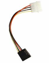
In general, each voltage is assigned its own color. You can familiarize yourself with them in detail if you read the plate on the PSU itself. In this case: Yellow - +12V Red - +5V Black - common Also, in some system units there are free 12 V connectors (Fig. 3), which are connected to the mother somewhere near the processor (+12 V power connector). You can also get food there.
And, of course, the main power connector (Fig. 4), where the entire range of voltages is collected. The mother is powered from this connector, so if there is an opportunity and there is no particular desire, it is better to leave it alone.
What do we want 1. Simple front panel illumination We use 12V from any free connector for this. Take the LEDs of any color you like, preferably bright. You can take LEDs of different colors (ladies' version - the device "New Year Tree"). IMPORTANT: Never connect LEDs in parallel!!! If you need to connect several diodes, then we connect in series and hang an additional resistor (Fig. 5), which we calculate by the formula:
R-resistance of the additional resistor E-supply voltage U-forward voltage diode n is the number of diodes in the garland (it is quite clear that the same diodes should be in the garland) I-direct current of diodes (at school they say that in series circuits the current is the same in any section and I agree with them).
Such garlands can be connected in parallel, but be aware of the current consumed (see clause 1.3.). The fastening of the garlands depends on the transparency of the front panel. You can hide the diodes inside (glue for example) or drill the front panel and, again, glue the diodes into these holes. The diameter of the most popular LED models is 5mm. 2. Dynamic backlight You can make, for example, a running fire. Here is the scheme
The running speed is selected by a capacitor (the lower, the faster) and is regulated by a trimming resistor R2 If not 10 garlands are used, as in the circuit, but less, then the input R is connected to the output following the last key. If there is a desire, then this scheme can be tied to the HDD indicator. To do this, a transistor optocoupler (any one found in the house) is placed in series with the indicator. It will strobe the clock generator.
It turns out that a light wave will run along with the indicator. As a load, you can use the very garlands with which it all began. 3. Gun meter One day, a cheerful dude asked me to put a pointer level meter from a tape recorder into his system unit. I don’t know who else has enough imagination for this, but I’ll show you the scheme. Tied to the same HDD indicator.
The rate of rise / fall of the indicator readings depends on the capacitor. 1 microfarad was enough for me. 4. Thermometer Measuring the temperature of the processor is a noble cause. To do this, there are sensors in the process itself and on the mother under it. If you do not trust all this, then you can blind your own thermometer. As a sensor, it is better to use any serviceable transistor that comes to hand.
As an indicator, you can use, for example, an indicator from a tape recorder with a total deflection current of 100 μA. If another indicator is planned, then R3 must be recalculated according to Ohm's law for the circuit section. As already mentioned, any transistors are suitable. Personally, I, most often, come across KT315 and KT3102. If only p-n-p transistors are at hand, then the power wires need to be swapped. In order for the thermometer to show the true temperature, you need to calibrate it according to the readings of a conventional room thermometer using R2. Naturally, not only percents can be measured, but also any other place in the system unit. For example HDD or chipset, or power button. Our task is only to install the VT1 sensor in the place where we want to measure the temperature. If there is no desire to admire the pointer device, then an LED can be used as an indicator, only for this you will have to supplement the circuit with a comparator
Transistors remain any, as well as op-amps, but the polarity change will end tragically for the entire device. A relay can be connected in parallel to the LED and R6, which switches on, for example, an additional fan. The supervisor will greatly simplify the circuit and reduce the size. For example MCP100. If you have such a wonderful thing, then you can blind according to this scheme
Resistor R2 sets the threshold (4,5 - 5V). Author: Ulitin Pavel A. (Soundoverlord), Chistopol (Tatarstan), Soundoverlord [bug]bk.ru. ICQ: 2-058-996; Publication: cxem.net
Artificial leather for touch emulation
15.04.2024 Petgugu Global cat litter
15.04.2024 The attractiveness of caring men
14.04.2024
▪ Firefox 3.6 will detect screen orientation ▪ MAX14001 - universal isolated discrete input ▪ Expanding the capabilities of the GSM / GPRS modem MAESTRO 100 ▪ Algae will help extract gold from hot springs ▪ TPS65135 - DC-DC bipolar power supply with one choke
▪ site section Chargers, accumulators, batteries. Article selection ▪ article For the construction of track car models. Tips for a modeller ▪ How did the struggle for the revival of the greatness of France take place? Detailed answer ▪ Amphiped article. Personal transport
Comments on the article: Paul I did not understand how the transistor VT1 switched on in the cut-off works in thermometers, please explain.
Home page | Library | Articles | Website map | Site Reviews
www.diagram.com.ua |


 where:


 Leave your comment on this article: