|
|


 Arabic
 Bengali
 Chinese
 English
 French
 German
 Hebrew
 Hindi
Hindi Italian
 Japanese
 Korean
 Malay
Malay Polish
 Portuguese
 Spanish
 Turkish
 Ukrainian
 Vietnamese
|
ENCYCLOPEDIA OF RADIO ELECTRONICS AND ELECTRICAL ENGINEERING Control bus I2C. Encyclopedia of Radio Electronics and Electrical Engineering
Encyclopedia of radio electronics and electrical engineering / Computers I2C is a two-wire interface developed by Philips. The original specification for the interface had a maximum data rate of 100 Kbps. However, over time, standards have appeared for faster modes of operation I2C. To one tire I2C, devices with different access rates can be connected, since the data rate is determined by the clock signal. The data transfer protocol is designed in such a way as to guarantee reliable reception of transmitted data. In data transfer, one device is the "Master", which initiates the data transfer and generates the synchronization signals. Another device "Slave" - starts transmission only on command from the "Master". In PIC16CXXX microcontrollers, the "Slave" mode of the device is implemented in hardware in the SSP module. The "Master" mode is implemented in software. Basic Terms Used in Describing Bus I Operation2C: Transmitter - a device that transmits data on a bus Receiver - a device that receives data from the bus "Master" - a device that initiates transmission and generates a clock signal "slave" - device accessed by "Master" Multi "Master" - bus mode I2C with more than one "Master" Arbitration - procedure to ensure that only one "Master" controls the bus Synchronization - procedure for synchronizing the clock signal from two or more devices The output stages of the clock (SCL) and data (SDA) conditioners must be made in open collector (drain) circuits to combine several outputs and connected to the power positive through an external resistor in order to have a "1" level on the bus when neither one device does not generate a "0" signal. The maximum capacitive load is limited to 400pF. Initialization and completion of data transfer When there is no data transfer on the bus, the SCL and SDA signals are high due to an external resistor. The START and STOP signals are generated by the "Master" to determine the start and end of data transfer, respectively. The START signal is generated by a high-to-low transition of the SDA signal while the SCL signal is high. The STOP signal is defined as the SDA transition from low to high when SCL is high. Thus, during data transmission, the SDA signal can only change when the SCL signal is low.
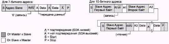
Device addressing on bus I2C Two address formats are used to address devices: Simple 7-bit format with R/W read/write bit;
and 10-bit format - in the first byte, the two most significant bits of the address and the write / read bit are transmitted, in the second byte, the low part of the address is transmitted.
Acceptance confirmation When transmitting data, after each transmitted byte, the receiver must acknowledge receipt of the byte with an ACK signal. If the "Slave" does not acknowledge receipt of the address or data byte, the "Master" must abort the transmission by issuing a STOP signal. When transmitting data from the "Slave" to the "Master", the "Master" generates acknowledgment signals for receiving data ACK. If the "Master" does not acknowledge the receipt of a byte, the "Slave" stops transmitting data, "releasing" the SDA line. The "Master" can then generate a STOP signal. For the data transfer delay, the "Slave" can set a logical zero, indicating the "Master" to wait. After the "release" of the SCL line, data transmission continues.
Data transfer from "Master" to "Slave"
Reading data from "Slave"
Using the re-START signal to access "Slave"
Multi-master mode Communication protocol I2C allows you to have more than one "Master" on the bus. Arbitration and synchronization functions are used to resolve conflicts on the bus during transfer initialization. Arbitration Arbitration is performed on the SDA line when the SCL line is high. A device that drives the SDA line high when another sends low loses the right to take "Master" and must go into "Slave" mode. A "master" that has lost the initiative on the bus can generate clock pulses until the end of the byte in which it lost its master properties.
Synchronization The clock on the bus occurs after arbitration has been performed on the SCL signal. When the SCL signal goes from high to low, all interested devices start counting the duration of the low level. Devices then begin to transition SCL from low to high according to the required data rate. After the level transitions from low to high, interested devices count the duration of the high level. The first device to pull the SCL signal low determines the clock parameters.
Publication: cxem.net
Artificial leather for touch emulation
15.04.2024 Petgugu Global cat litter
15.04.2024 The attractiveness of caring men
14.04.2024
▪ The pendant will protect from criminals ▪ Toshiba HK3E2 Solid State Drives
▪ site section Power supplies. Article selection ▪ Article Skin protection. Basics of safe life ▪ article What is the age of a woman called Balzac and why? Detailed answer ▪ article Actions in case of severe freezing. Tourist tips ▪ article Automotive voltage regulator. Encyclopedia of radio electronics and electrical engineering ▪ article Modeling propellers. physical experiment
Home page | Library | Articles | Website map | Site Reviews
www.diagram.com.ua |


 Leave your comment on this article: