|
|
ENCYCLOPEDIA OF RADIO ELECTRONICS AND ELECTRICAL ENGINEERING Automotive voltage regulator. Encyclopedia of radio electronics and electrical engineering
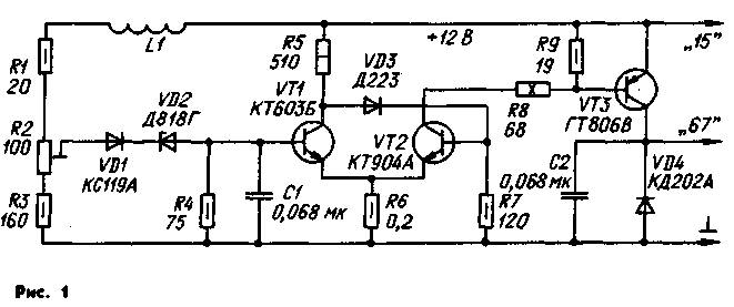
Encyclopedia of radio electronics and electrical engineering / Automobile. Electronic devices The electronic voltage regulator in the automotive electrical system has already established itself as a reliable, stable and durable unit. One of the variants of such a regulator is described below, which has been tested for a long time on different cars and showed good results. The features of the regulator are the use of a Schmitt trigger in the control unit of the output transistor and the presence of a temperature dependence of the regulated voltage. The regulator is mounted in the body of the RR-380 relay-regulator and completely replaces it. The first of these features made it possible to reduce the power dissipation in the output transistor due to its high switching speed. The second allows you to automatically reduce the charging voltage of the battery when the temperature in the engine compartment rises. It is known that the charging voltage in summer should be lower than in winter. Failure to comply with this condition leads to electrolyte boiling in summer and undercharging of the battery in winter. Schematic diagram of the electronic regulator is shown in fig. 1. The regulator consists of three functional units: an input control unit consisting of a resistive voltage divider R1-R3, a stabistor VD1 and a zener diode VD2, a Schmitt trigger on VT1.VT2 transistors and an output switch on a VT3 transistor and a VD4 diode. Inductor L1 serves to reduce the voltage ripple at the trigger input, which degrade the efficiency of regulation.
Elements VD1 and VD2 form an exemplary voltage. The voltage supplied to the input of the Schmitt trigger is equal to the difference between the regulated part of the input voltage and the reference voltage. Due to the temperature dependence of the voltage on the stabistor VD1 and the emitter junction of the transistor VT1, the reference voltage decreases with increasing temperature. As a result, the voltage supplied to the battery decreases by about 10 mV with an increase in temperature by 1 ° C, which is necessary for the correct operation of the battery. The Schmitt trigger is made according to the classical scheme. Capacitor C1 prevents high-frequency excitation of this transistor when it is in linear mode, and does not affect the switching speed of the flip-flop. The difference between the switching voltage thresholds is determined by the ratio of the values of the resistors R6 and R8 and is approximately 0,03 V.
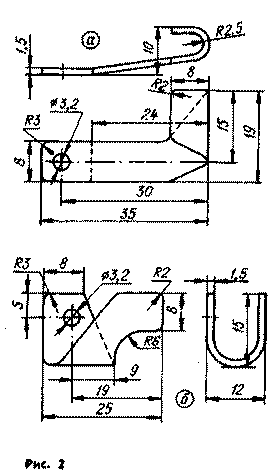
Transistor VT3 of the electronic key is saturated in the open state, so that at a collector current of 3 A, only 0,25 V drops on it. Due to the good speed of the transistor and the pulse control mode with a steep front and a drop in the control voltage pulses, the power dissipated on the transistor does not exceed 0,5 .0,8 W at medium and high values of the generator rotor speed and 3 W at low ones. With such power dissipation, there is no fundamental need for a heat sink for the VTXNUMX transistor. Diode VD4 serves to protect the transistor VT3 from self-induction voltage surges from the excitation winding of the generator that occur when the transistor is closed. In this case, the self-induction current closes through the VD4 diode, decreasing exponentially. Capacitor C2 eliminates interference associated with the operation of the regulator and which can penetrate the vehicle's on-board network. Electronic controller structurally most convenient to perform based on the existing relay-regulator RR-380. All parts are removed from its base, except for the inductor and a 19 ohm wire resistor located under the mounting platform (this inductor is L1 in the diagram in Fig. 1. and the resistor is R9). The plastic connector with contact strips and the insulating gasket should also be left. Most of the regulator elements are located on two printed circuit boardsmade of foil fiberglass 2 mm thick. Resistors R8 and R9, inductor L1, diode VD4 and transistor VT3 are installed outside the boards. The boards and the VT3 transistor are screwed to a square made of sheet brass or steel 2 mm thick, attracted to the base with a screw (with a nut) of the VD4 diode (KD202A). The drawing of the square is presented on the tab. Diode VD4 is installed in hole A. The tuning resistor R2 is installed on the board 1 with a set screw outward 'on the side of the printed conductors. Transistor VT1 is glued into the hole of the board 2. Resistor R8 - PEV-10 - is soldered with leads to two brass petals (Fig. 2, a and b), which are fixed with M380 screws in the holes of the base, which served in the PP-5,5 regulator for mounting resistor XNUMX, XNUMX ohm. Board 1 with the details of the input node is recommended to be installed on the square after it is fixed on the base. Then solder all the jumpers between the boards and parts outside the boards. Jumpers are made of tinned copper wire with a diameter of 0,5 mm. The regulator uses a tuning resistor SP5-14; you can use resistors with other ratings, provided that the total resistance R2 + R3 is maintained. Resistor R6 is made of a constantan wire with a diameter of about 0,3 mm, wound around any OMLT-0,5 resistor. Instead of a 68 ohm resistor (R8), it is permissible to use the same resistors with a resistance of 51 to 75 ohms. Capacitors - KM-5a-NZO, with a capacity of up to 0,1 microfarads. Instead of KT603B, you can use any transistor from this series, as well as KT608A, KT608B; instead of KT904A - KT904B, KT926A, KT926B; instead of GT806V - any of the GT806, 1T813 series. When testing the regulator, instead of the GT806V transistor, the P217B transistor was switched on for testing. Although the heating of the case of this transistor was somewhat higher than that of the GT806V, the use of P216 transistors turned out to be quite acceptable. P216A, P217A - P217V. Stabistor KS119A can be replaced by KS113A. Instead of D818G, it is possible to use other zener diodes of this series, however, there may be difficulties with the temperature setting of the regulator, to overcome which it will be necessary to select resistors R1 and R3 (while maintaining the total resistance R1 + R2 + R3 in the range from 250 to 300 ohms). Instead of D223, diodes D219A, D220A, D220B, KD504A are suitable; instead of KD202A - any of this series. You can set up an electronic regulator directly on the car, but it is better to check it first by connecting it to a regulated power supply with a voltage of up to 14 V with a small ripple level (with a range of not more than 0,05 V). Before turning on the screw of the tuning resistor R2, turn it all the way clockwise, and an incandescent lamp (CM67-28 or another) is connected to terminal 20 and a common wire for a voltage of 12 ... 27 V; Turn on the power supply and rotate the screw of the resistor R2 counterclockwise until the lamp ignites. After that, the regulator is installed on the car. A voltmeter with an accuracy class of at least 1.5 measures the voltage directly at the terminals of the battery. Before starting the engine, check the voltage between the collector and emitter of the transistor VT3, it should be no more than 0,3 V. Start the engine, set the average speed of the generator rotor and the screw of the resistor R2 bring the voltage at the battery terminals to the required level at 40 ° C - 13,9 .14 ... 20 V, at 14,2 ° С - 14,3 ... 0 V. at 14.4 - 14.5 ... XNUMX V. In conclusion, increase the frequency of rotation of the generator rotor to the maximum, the voltage at the battery outputs should increase by no more than 0,1 ... between the positive terminal of the battery and the terminal "0,15" of the voltage regulator. By the way, for this reason, with a serviceable, fully charged battery, short flashes of the control lamp on the dashboard of the car may be observed while driving. Several copies of the electronic regulator have been tested for more than 5 years and have shown good results. At an outside temperature of +35 ° C, after reaching the maximum temperature in the engine compartment (during a long drive), the voltage at the battery terminals decreased to 13,9 V, while the charging current was 0,7 A. At a temperature of -10 ° C, the voltage increased up to 14.4 V, and the charging current was in the range of 0,8 ... 1 A. Author: A. Korobkov, Lyubertsy; Publication: N. Bolshakov, rf.atnn.ru
Artificial leather for touch emulation
15.04.2024 Petgugu Global cat litter
15.04.2024 The attractiveness of caring men
14.04.2024
▪ TV controlled by the power of thought ▪ Converting hydrogen to metal ▪ Intel Optane DC - the first RAM with 3D XPoint chips ▪ Some genes wake up after death ▪ By 2025, HDD capacity will grow to 100 TB
▪ section of the site The most important scientific discoveries. Article selection ▪ article by Joseph Addison. Famous aphorisms ▪ article When did the Red Cross start to operate? Detailed answer ▪ Article Business Consultant. Job description ▪ article In spot welding mode. Encyclopedia of radio electronics and electrical engineering ▪ Rope Turning article. Focus Secret
Comments on the article: Konstantin Thank you very much! Grandfather The relay according to this scheme works fine, I have been at the VAZ for more than 15 years, it keeps the voltage of the on-board network very stable when any consumers are turned on (brushes, light, near, far, foglights, rear window heating).
Home page | Library | Articles | Website map | Site Reviews www.diagram.com.ua |


 Arabic
 Bengali
 Chinese
 English
 French
 German
 Hebrew
 Hindi
Hindi Italian
 Japanese
 Korean
 Malay
Malay Polish
 Portuguese
 Spanish
 Turkish
 Ukrainian
 Vietnamese


 Leave your comment on this article: