|
|


 Arabic
 Bengali
 Chinese
 English
 French
 German
 Hebrew
 Hindi
Hindi Italian
 Japanese
 Korean
 Malay
Malay Polish
 Portuguese
 Spanish
 Turkish
 Ukrainian
 Vietnamese
|
ENCYCLOPEDIA OF RADIO ELECTRONICS AND ELECTRICAL ENGINEERING Instructions for the installation of local networks. Encyclopedia of radio electronics and electrical engineering
Encyclopedia of radio electronics and electrical engineering / Computers Installation and methods of working with various data transmission media, in my opinion, are one of the most interesting topics for many users: after all, it is the ability to work with a data transmission medium from scratch that distinguishes an experienced "networker" from a beginner. This material, in fact, is not intended for specialists in installation of local networks, since it will deal with things that are well known and familiar to them - about the basics of installation work. Its purpose, rather, is to explain the basic concepts and give the necessary guidance to those who, not being an expert in this field, nevertheless have to do it, - for example, setting up a local network at home. Installing a cable system is not as simple as it might seem at first glance. Proper installation of the connector on the cable is very important, especially when it comes to twisted pair cable and fiber optic cable. local computer network It is primarily a signaling medium. Without a transmission medium, the network cannot be, by definition, just as there can be no breathing without air. The transmission medium can be conditionally divided into limited and unlimited. The restricted environment is, simply put, the cable. As an example of an unrestricted environment, we can take the open air, which transmits RadioEthernet signals. As a signal transmission medium in local networks, as a rule, the following are used:
Coaxial cables At the beginning of the development of local networks, coaxial cable was the most common transmission medium. It was used and is used mainly in Ethernet networks and partly ARCnet. There are "thick" and "thin" cables. "Thick Ethernet" is generally used as follows. It is laid along the perimeter of the room or building, and 50-ohm terminators are installed at its ends. Due to its thickness and rigidity, the cable cannot be connected directly to the network board. Therefore, "vampires" are installed on the cable in the right places - special devices that pierce the cable sheath and connect to its braid and central core. The "Vampire" sits on the cable so firmly that once installed it cannot be removed without a special tool. A transceiver, in turn, is connected to the "vampire" - a device that matches the network card and cable. And finally, a flexible cable with 15-pin connectors on both ends is connected to the transceiver - the other end is connected to the AUI (attachment unit interface) connector on the network board. All these difficulties were justified by only one thing - the allowable maximum length of a "thick" coaxial cable is 500 meters. Accordingly, one such cable can serve a much larger area than a "thin" cable, the maximum allowable length of which is, as you know, 185 meters. If you have some imagination, you can imagine that a "thick" coaxial cable is an Ethernet hub distributed in space, only completely passive and does not require power. It has no other advantages, but there are more than enough drawbacks - first of all, the high cost of the cable itself (about $ 2,5 per meter), the need to use special devices for installation ($ 25-30 per piece), the inconvenience of laying, etc. . This gradually led to the fact that "fat Ethernet" slowly but surely disappeared from the scene, and is currently not used anywhere. "Thin Ethernet" is much more widespread than its "fat" counterpart. The principle of use is the same, but thanks to the flexibility of the cable, it can be connected directly to the network board. To connect the cable, BNC connectors (bayonet nut connector) are used, which are installed on the cable itself, and T-connectors, which serve to divert the signal from the cable to the network board. BNC connectors are crimped and collapsible (an example of a collapsible connector is the domestic connector SR-50-74F).
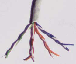
T-connector To mount the connector on the cable, you will need either a special crimping tool or a soldering iron and pliers. The cable must be prepared as follows: 1. Carefully cut so that its end is even. Attach the metal sleeve (piece of tubing) that comes with the BNC connector to the cable. 2. Remove the outer plastic jacket from the cable for a length of approximately 20 mm. Be careful not to damage any conductor of the braid if possible. 3. Carefully unwind the braid and spread it apart. Remove the insulation from the center conductor for a length of approximately 5 mm. 4. Install the center conductor into the pin that is also supplied with the BNC connector. Using a special tool, securely crimp the pin, fixing the conductor in it, or solder the conductor into the pin. When soldering, be especially careful and attentive - poor soldering after a while will cause network failures, and it will be quite difficult to localize this place. 5. Insert the center conductor with the pin installed on it into the body of the connector until it clicks into place. A click means that the pin is seated in its place in the connector and fixed there. 6. Evenly distribute the braided conductors over the connector surface, if necessary, cut them to the desired length. Slide the metal sleeve onto the connector. 7. Using a special tool (or pliers), gently crimp the sleeve until the braid is in good contact with the connector. Do not crimp too hard - you may damage the connector or pinch the insulation of the center conductor. The latter can lead to unstable operation of the entire network. But it is also impossible to crimp too weakly - poor contact of the cable sheath with the connector will also lead to failures. I note that the domestic SR-50 connector is mounted in much the same way, except that the braid in it is embedded in a special split sleeve and secured with a nut. In some cases, this may even be more convenient. Twisted pair cables Twisted pair (UTP / STP, unshielded / shielded twisted pair) is currently the most common signal transmission medium in local networks. UTP/STP cables are used in Ethernet, Token Ring, and ARCnet networks. They differ by category (depending on the bandwidth) and type of conductor (flexible or solid). In a Category 5 cable, as a rule, there are eight conductors intertwined in pairs (that is, four pairs).
UTP cable A structured cabling system based on Category 5 twisted pair has a very high flexibility in use. Her idea is as follows. At least two (recommended three) four-pair RJ-45 sockets are installed for each workstation. Each of them is connected with a separate cable of the 5th category to a cross or patch panel installed in a special room - a server room. Cables from all workplaces are brought into this room, as well as city telephone inputs, dedicated lines for connecting to global networks, etc. In the room, of course, servers are mounted, as well as an office PBX, alarm systems and other communication equipment. Due to the fact that the cables from all workplaces are brought together on a common panel, any socket can be used both to connect the workplace to the LAN, and for telephony, or anything else. Let's say two outlets at the workplace were connected to a computer and a printer, and the third one was connected to a telephone exchange. In the process of work, it became necessary to remove the printer from the workplace and install a second phone instead. There is nothing simpler - the patch cord of the corresponding outlet is disconnected from the hub and switched to a telephone cross, which will take the network administrator no more than a few minutes.
Socket for 2 ports A patch panel, or connection panel, is a group of RJ-45 receptacles mounted on a 19" wide plate. This is a standard size for universal communication cabinets - racks (racks) in which equipment is installed (hubs, servers, uninterruptible power supplies, etc.). On the reverse side of the panel are mounted connectors into which cables are mounted. The cross, unlike the patch panel, does not have sockets. Instead, it carries special connecting modules. In this case, its advantage over the patch panel is that when it is used in telephony, the inputs can be connected to each other not with special patch cords, but with ordinary wires. In addition, the cross can be mounted directly on the wall - it does not require a communication cabinet. Indeed, it makes no sense to purchase an expensive communication closet if your entire network consists of one or two dozen computers and a server. Cables with stranded flexible conductors are used as patch cords, that is, connecting cables between a socket and a network card, or between sockets on a connection panel or distribution box. Cables with single-core conductors - for laying the actual cable system. The installation of connectors and sockets on these cables is completely identical, but usually cables with single-core conductors are mounted on sockets of user workplaces, connection panels and cross-connects, and connectors are installed on flexible connecting cables.
Patch panel As a rule, the following types of connectors are used:
RJ-45 connector Depending on what you need to switch with, various patch cords are used: "45-45" (on each side with an RJ-45 connector), "110-45" (on one side S110, on the other - RJ-45 ) or "110-110". For the installation of RJ-11, RJ-12 and RJ-45 connectors, special crimping tools are used, which differ in the number of knives (6 or 8) and the size of the socket for fixing the connector. As an example, consider installing a Category 5 cable to an RJ-45 connector. 1. Carefully cut the end of the cable. The end of the cable must be straight. 2. Using a special tool, remove the outer insulation from the cable for a length of approximately 30 mm and cut the thread embedded in the cable (the thread is designed to make it easier to strip the insulation from the cable for a long length). Any damage (cuts) to the insulation of the conductors is absolutely unacceptable - that is why it is advisable to use a special tool, the cutter blade of which protrudes exactly the thickness of the outer insulation. 3. Carefully spread, unwind and align the conductors. Align them in one row, while observing the color coding. The two most common color pairing standards are T568A (recommended by Siemon) and T568B (recommended by AT&T and actually the most commonly used).
On the RJ-45 connector, the colors of the conductors are arranged as follows:
The conductors must be placed strictly in one row, without overlapping each other. Holding them with one hand, cut the conductors evenly with the other so that they protrude 8-10 mm above the outer winding. 4. Keeping the connector latch down, insert the cable into the connector. Each conductor must fall into its place in the connector and rest against the limiter. Before crimping the connector, make sure that you have not made a mistake in the wiring. With incorrect wiring, in addition to the lack of correspondence to the pin numbers at the ends of the cable, which is easily detected using the simplest tester, a more unpleasant thing is possible - the appearance of "splitted pairs" (splitted pairs). To detect this marriage, a conventional tester is not enough, since the electrical contact between the corresponding contacts at the ends of the cable is ensured and everything seems to be normal. But such a cable will never be able to provide normal connection quality even in a 10-megabit network over a distance of more than 40-50 meters. Therefore, you need to be careful and take your time, especially if you do not have enough experience. 5. Insert the connector into the socket on the crimping tool and crimp it to the stop-stop on the tool. This will lock the latch on the connector into place, holding the cable in place in the connector. The contact blades of the connector will each cut into their own conductor, ensuring reliable contact. RJ-11 and RJ-12 connectors can be mounted in the same way using the appropriate tool. No special crimping tool is required to install the S110 connector. The connector itself is delivered unassembled. By the way, unlike "disposable" RJ connectors, the S110 connector allows multiple disassembly and assembly, which is very convenient. The sequence of actions during installation is as follows: 1. Strip the outer insulation of the cable for a length of approximately 40 mm, spread the pairs of conductors apart without unwinding them. 2. Fasten the cable (in the half of the connector on which there is no contact group) with a plastic tie and cut off the resulting "tail". 3. Carefully place each conductor into the organizer on the connector. Do not unwind the pair more than required - this will degrade the performance of the entire cable connection. The sequence of laying pairs is the usual - blue-orange-green-brown; while the light wire of each pair is laid first. 4. Use a sharp tool (side cutters or knife) to cut each conductor around the edge of the connector. 5. Replace the second half of the connector and crimp it with your hands until all the latches click into place. In this case, the knives of the contact group will cut into the conductors, providing contact. Fiber optic cable Fiber optic cables are the most promising and fastest signal propagation medium for local networks and telephony. In local area networks, fiber optic cables are used to work using the ATM and FDDI protocols.
Connector stripper and crimp tool Optical fiber, as its name implies, transmits signals using pulses of light radiation. Semiconductor lasers and LEDs are used as light sources. Optical fiber is divided into single-mode and multi-mode. Single-mode fiber is very thin, its diameter is about 10 microns. Due to this, the light pulse passing through the fiber is less often reflected from its inner surface, which provides less attenuation. Accordingly, single-mode fiber provides greater range without the use of repeaters. The theoretical throughput of single-mode fiber is 10 Gbps. Its main disadvantages are high cost and high complexity of installation. Single-mode fiber is mainly used in telephony. Multimode fiber has a larger diameter - 50 or 62,5 microns. This type of optical fiber is most often used in computer networks. The greater attenuation in multimode fiber is due to the higher dispersion of light in it, due to which its throughput is significantly lower - theoretically it is 2,5 Gb / s. Special connectors are used to connect the optical cable to active equipment. The most common connectors are SC and ST. Mounting connectors on a fiber optic cable is a very demanding operation that requires experience and special training, so you should not do this at home without being a specialist. If you are already "impatient" to build a network using fiber optics, it is easier to purchase cables with connectors. However, given the cost of cable, connectors, and active optical equipment, it can be assumed that this equipment will not be used in home and small LANs for a long time. Publication: cxem.net
Artificial leather for touch emulation
15.04.2024 Petgugu Global cat litter
15.04.2024 The attractiveness of caring men
14.04.2024
▪ Image sensors for car headlights ▪ Alternative to gold in chips ▪ Celeron 1019Y processor for ultrabooks ▪ Creation of an artificial uterus
▪ section of the site Home workshop. Article selection ▪ article Normal human anatomy. Lecture notes ▪ article Why is a movie advertisement called a trailer? Detailed answer ▪ Article Analyst. Job description ▪ article A woman floats on a table. Focus Secret
Home page | Library | Articles | Website map | Site Reviews
www.diagram.com.ua |


 Leave your comment on this article: