|
|


 Arabic
 Bengali
 Chinese
 English
 French
 German
 Hebrew
 Hindi
Hindi Italian
 Japanese
 Korean
 Malay
Malay Polish
 Portuguese
 Spanish
 Turkish
 Ukrainian
 Vietnamese
|
ENCYCLOPEDIA OF RADIO ELECTRONICS AND ELECTRICAL ENGINEERING Transistor clock. Encyclopedia of radio electronics and electrical engineering
Encyclopedia of radio electronics and electrical engineering / Clocks, timers, relays, load switches The main element of conventional mechanical watches is the pendulum or balance, which is driven by a weight or spring. Such watches require regular and frequent winding, which creates certain inconveniences. Many designers have been working on the problem of creating watches without weights and springs for a long time, as a result, electromechanical watches appeared. In them, the pendulum is set in motion by an electromagnet, which is powered by an electric current source. When the pendulum approaches the equilibrium position (Fig. 1), the contacts associated with it close and current flows through the electromagnet winding. An anchor made of soft iron is fixed on the pendulum, which is attracted by a stationary electromagnet.
Electromechanical watches are very economical in battery power and have good accuracy. But they also have a weak point - the contacts that close the circuit of the electromagnet. After all, in just one year they have to close millions of times, so after a while the electric clock begins to work inaccurately. And if the watch is very small, for example, a wristwatch, then the miniature contacts in them work even more unreliably. With the advent of transistors, it became possible to create contactless electric watches. scheme electric non-contact clock on a transistor is shown in fig. 2. A permanent magnet is fixed on the pendulum, during the movement of which an emf is induced in the turns of a fixed coil. One of the windings of the coil is connected between the base and the emitter of the transistor, the second - in the collector circuit.
The center of the pendulum (magnet) crosses the axis of the coil in the equilibrium position. When the pendulum oscillates in coil L1, an emf is induced, the shape of which is illustrated by curve 1 (Fig. 3). In this figure, the curves drawn with a solid line represent the diagrams of voltages and currents that occur when the pendulum moves from left to right, and the dotted line - from right to left. The ends of the winding of the coil L1 are connected so that when the pendulum approaches the equilibrium position, a voltage negative relative to the emitter appears at the base of the transistor. It occurs when a magnet approaches the coil, due to an increase in the magnetic flux crossing its turns. In the equilibrium position, the magnetic flux through the coil reaches its maximum. At this point, the voltage becomes zero. Further, the magnetic flux begins to decrease and the emf changes sign to the opposite. When the magnet moves away from the coil, the voltage at its ends almost disappears. During the second half-cycle, the picture repeats itself: when the magnet approaches the coil, such an emf is induced in the winding L1 that the voltage at the base is negative. Under the action of this voltage pulse, a current passes in the base circuit (curve 2) and the transistor is unlocked (Fig. 3).
The direction of the turns of the coil L2, included in the collector circuit, is such that when the collector current passes through it (curve 3), the magnet is attracted to the coil. His movement is accelerating. The oscillation frequency of a pendulum, as in a conventional clock, is almost completely determined by its physical parameters: length and mass distribution. The mass of the pendulum is mainly determined by the magnet and the details of its attachment. A pointer mechanism is connected to the pendulum with a dial, and the clock is ready. Clock design. For the manufacture of clocks on a transistor, any pendulum clock or "clock" is quite suitable. In them, it is only necessary to remake the trigger and, of course, remove the spring or weight; their functions will be performed by the battery. In an ordinary clock, the escapement that sets the pendulum in motion has the form shown in Fig. 4a. It must be modified as shown in Fig. 4b. A rocker arm 1 is soldered onto the axle 2, on which the earring 3 is freely suspended. When the pendulum moves to the left, the earring slides along the beveled side of the tooth of the ratchet wheel 4 and, under the influence of its gravity, jumps off its top into the gap between the teeth. When the pendulum moves to the right, the earring rests against the steep side of the tooth and turns the ratchet wheel to the left by one tooth. To fix the position of the wheel and prevent it from turning to the right, one edge of the petal-dog 5 lies on top of it. The second edge of the petal rotates freely around axis 6. When the ratchet wheel rotates to the left, the petal slides along the beveled edges of the teeth and, jumping off their tops, rests into the sharp edges of the teeth.
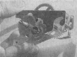
The assembled clock mechanism, made from conventional clocks, is shown in fig. 5. Rocker, earring and petal-dog in this watch are made of tin. Any magnet can be used. Its volume should not be less than 3-4 cm3, since it must hold a load of 100-200 g. In the described design, a ring magnet from a loudspeaker with a diameter of 35 mm is used. To adjust the movement of the watch, the magnet must be mounted so that it can move up and down. If the clock is fast, then the pendulum (magnet) must be lowered.
Any alloy transistors, for example, type P2-P13, can work in a clock generator (Fig. 15). The operation of the generator does not depend on the current gain of the transistor. Diode D1 can be used type D7B-D7Zh. Instead of a diode, you can use the emitter or collector junction of a germanium alloy transistor, in which the emitter or collector terminal has come off. If a transistor with npn conductivity is used in the generator (Fig. 2), then the polarity of the battery and diode D1 should be reversed. The electromagnet coil can be wound on a plastic or paper frame with an inner diameter of 20, an outer diameter of 48 and a width of 8 mm. It is necessary to wind the coil in two wires in bulk until it is filled. Wire diameter - 0,09-0,15 mm. After winding, it is necessary to check whether there are any short circuits between the two windings obtained. The beginning of one winding is connected to the end of the other, and the output of the emitter of the transistor is connected to this point. Author: N. Goryunov, A. Pushkin; Publication: N. Bolshakov, rf.atnn.ru
Machine for thinning flowers in gardens
02.05.2024 Advanced Infrared Microscope
02.05.2024 Air trap for insects
01.05.2024
▪ Toyota Mirai hydrogen sedan billboards purify the air
▪ section of the site Palindromes. Article selection ▪ Philosopher's Stone article. Popular expression ▪ article Why is a mirror considered dangerous? Detailed answer ▪ article Voronet spiky red. Legends, cultivation, methods of application
Comments on the article: Jury The battery voltage is not specified. Sergei In the 1,5s, I redid a clock that hung in our kitchen. They began to fail and this development came across. Now in the garage there is a rarity of the same design (the neighbors brought it for repairs - it's a pity to throw it away). Set out to replicate the design. And it's so good that there was that description and scheme, according to which I remade the clock then, while still a schoolboy. Voltage 373 volts. Then the battery element XNUMX was offered, like a big one, it worked for a long time. Thanks to the developers of the site for saving this design. Victor Voltage 1,5 volts. Then the battery element 373 was offered, like a big one, it worked for a long time. Thanks to the developers of the site for saving this design. UK I played with this scheme 40 years ago. Germanium transistors worked better in it, up to 0,9 V supply.
Home page | Library | Articles | Website map | Site Reviews
www.diagram.com.ua |

 Leave your comment on this article: