|
|


 Arabic
 Bengali
 Chinese
 English
 French
 German
 Hebrew
 Hindi
Hindi Italian
 Japanese
 Korean
 Malay
Malay Polish
 Portuguese
 Spanish
 Turkish
 Ukrainian
 Vietnamese
|
ENCYCLOPEDIA OF RADIO ELECTRONICS AND ELECTRICAL ENGINEERING Two light beacons. Encyclopedia of radio electronics and electrical engineering
Encyclopedia of radio electronics and electrical engineering / Beginner radio amateur Often in poor lighting conditions, it becomes necessary to designate one or another object. The described device will help to do this. The composition of the light beacon usually includes a generator of electrical impulses, a key - electronic (on a transistor) or on electromagnetic relays, as well as a light source, for example, an incandescent lamp. In the first version of the beacon (Fig. 1), the main elements are the DD1 microcircuit and the VT1 transistor, which is composite in internal structure.
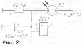
On the elements DD1.1 - DD1.3, a rectangular pulse generator is made, on DD1.4 - a buffer stage, and on the transistor VT1 - an electronic key that controls the incandescent lamp EL1. Unlike traditional logic element generators, in which a frequency-setting capacitor is connected between the input of one and the output of another logic element, in this device one of the capacitor leads is connected to a common wire. This ensures a constant polarity across the capacitor and allows the use of a high polarity capacitor. The cascade on the elements DD1.1, DD1.2 acts as a voltage comparator. Positive feedback is carried out through a resistive divider R1R2, and negative feedback through resistors R3, R4 and diodes VD1, VD2. The capacitor C1 is charged through the diode VD1 and the resistor R3, the charging time is determined by the capacitance of the capacitor and the resistance of the resistor. During this time, the output of the element DD1.4 will be a high logic level, so the transistor is open, the lamp is on. The capacitor is discharged through the diode VD2 and the resistor R4, the duration of this process is determined by the capacitance of the capacitor and the resistance of the resistor R4. In this mode, the output of the DD1.4 element will be a low logic level, the transistor is closed, the lamp is off. By changing the values of these resistors and the capacitance of the capacitor, you can change the duration of the lamp on and the interval between switching on. You can power the device from a battery of galvanic cells or batteries. The supply voltage is supplied by the switch SA1. The beacon works at any time of the day. In order for it to automatically turn on in the dark, it is necessary to supplement it with a photosensitive element (for example, a photoresistor, phototransistor), and change the circuit in accordance with Fig. 2.
During daylight hours, the resistance of the photoresistor R7 is small and the input of the DD1.1 element will be a high logic level. The generator does not work at the output of the element DD1.4 low logic level, the transistor is closed. When it becomes dark, the resistance of the photoresistor will increase, a low logic level will appear at the input of the DD1.1 element, the generator will work, the lamp will flash periodically. The threshold for the operation of automation is set by a trimming resistor R6 More reliable operation of the device can be ensured by introducing a backup channel into it, since the most unreliable element is an incandescent lamp, especially if it operates in a pulsed mode, which reduces its service life. If it burns out, the beacon will be useless. Therefore, in some cases, it is advisable to introduce a backup channel, which is implemented in the second version of the device (Fig. 3).
The backup channel is assembled on the DD1.4 element, the VT2 transistor and the EL2 lamp. If the lamp EL1 is working, then a high logic level from the collector of the transistor VT1 through the resistor R7 will go to one of the inputs of the logic element and its output will be a low logic level. Transistor VT2 is closed, lamp EL2 is off. For a short time, while the EL1 lamp is on, there is a low logic level on the collector of the transistor VT1, but the capacitor C3 does not have time to discharge and the EL2 lamp remains in the same state. If the EL1 lamp burns out, the collector of the transistor VT1 will constantly have a low logic level, the capacitor C3 will be discharged, the EL2 lamp will flash In addition to those indicated in the diagrams, transistors KT972B, KT829A-KT829G can be used in devices. Each of them can be replaced by two connected according to the circuit of a composite transistor (Fig. 4, a).
To switch a lamp that consumes high current (more than 10 ... 15 A), a powerful field-effect switching transistor 1RLR2905 (Fig. 4,b) or similar is suitable, which can be selected from the reference table given in the article "Powerful field-effect switching transistors from International Rectifier "in "Radio", 2001, No. 5, p. 45. Diodes - any of the KD102 series. KD103. KD521, KD522. Polar capacitors - K50-6 or similar imported ones. Fixed resistors - MLT, S2-33, P1-4, trimmer - SPZ-19, photoresistor - SF-4, SF-6, but it is permissible to install the FT-1k phototransistor by connecting it to the EL1 lamp with a collector. Most of the parts are mounted on boards made of one-sided foil fiberglass: a sketch for the first version of the beacon is shown in fig. 5, for the second - in Fig. 6. Each board is placed in a housing made of insulating material, and the photosensitive element is positioned so as to exclude optical communication between it and the incandescent lamp.
Establishing a beacon comes down to setting the required duration of the lamp burning and pause by selecting resistors R3, R4 and capacitor C1, as well as the desired threshold for triggering a photo device with a tuning resistor. Author: I. Nechaev, Kursk
Traffic noise delays the growth of chicks
06.05.2024 Wireless speaker Samsung Music Frame HW-LS60D
06.05.2024 A New Way to Control and Manipulate Optical Signals
05.05.2024
▪ Women's brains age more slowly ▪ The new USB connector will not be incompatible with the current one. ▪ MWC 2015: HTC Vive Virtual Reality Headset ▪ Video card GIGABYTE GeForce GTX 1650 D6 Eagle OC ▪ Internet broadcast of digital video
▪ section of the site Wonders of nature. Article selection ▪ article Drink the cup to the bottom. Drink the cup to the bottom. Popular expression ▪ article What is a sandwich made of? Detailed answer ▪ article Working near existing railway lines and highways. Standard instruction on labor protection
Home page | Library | Articles | Website map | Site Reviews
www.diagram.com.ua |


 Leave your comment on this article: