|
|


 Arabic
 Bengali
 Chinese
 English
 French
 German
 Hebrew
 Hindi
Hindi Italian
 Japanese
 Korean
 Malay
Malay Polish
 Portuguese
 Spanish
 Turkish
 Ukrainian
 Vietnamese
|
ENCYCLOPEDIA OF RADIO ELECTRONICS AND ELECTRICAL ENGINEERING Low-voltage supply voltage indicator. Encyclopedia of radio electronics and electrical engineering
Encyclopedia of radio electronics and electrical engineering / Beginner radio amateur The proposed device on LED indicators (see figure) allows you to show the voltage on a power source consisting of two batteries or galvanic cells with a sufficient degree of accuracy.
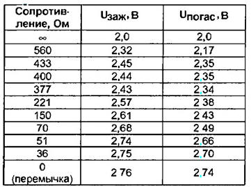
With fully charged batteries, the voltage on the battery is 2,4 V (for "fresh" galvanic cells 3 V). In this case, all three LEDs light up. With a smooth decrease in voltage to 2,3 V, HL3 will first turn off, and then, at a voltage of 2 15 V, HL2 will turn off. With a further decrease in voltage to 2 V, HL1 will turn off. This indicates that the batteries are completely discharged and need to be replaced or recharged. When using galvanic cells, the switching thresholds must be set to voltages of 2,45 and 2,7 V, respectively. The ignition threshold of the HL2 and HL3 LEDs is determined by the resistances of the resistors R1 and R2 The principle of operation of the indicator cell is based on the use of the avalanche switching property of transistors in a dinistor circuit. Until a certain voltage (opening voltage) is reached, the transistors are closed and the current through them is negligible. When the voltage exceeds the specified one, the transistors open like an avalanche, the flowing current increases and the voltage across the transistors drops to 0,5 ... 0,8 V. When the voltage decreases, the current decreases, and when it decreases below the holding current, the transistors close. This property can be used to control any device. For example, turn off the player or turn on the sound alarm when the voltage on the batteries drops below the permissible level. The resistor introduces negative current feedback into the cell circuit. By changing the resistance of the resistor, you can adjust the threshold voltage for opening and closing transistors. If the resistance of the resistor is zero (i.e., a jumper is installed), then the p-n junctions of the base-emitter of transistors are equivalent to a conventional diode. In this device, it is desirable to use integrated transistor assemblies. This is due to the fact that the parameters of transistors change over a wide range from temperature changes, which can affect the accuracy of the indication. It is allowed to use discrete transistors of the KT315, KT361, KT3102, KT3107 series. All transistors must have a base current transfer coefficient of at least 80. LEDs can be used with any of the AL307 series. For transistors with a transfer coefficient of about 80, the resistances of the resistors obtained experimentally are shown in the table.
The disadvantage of the device is a small hysteresis of turning on and off the indicator cell. The indicator device is sensitive to excess supply voltage. When connecting the device to points with a voltage exceeding the indicator supply voltage, the LEDs may fail. Installing a resistor in series with the LED reduces the brightness of the glow. For self-powered devices, the efficiency of the indicator is important. Therefore, you need to turn on the power of the indicator by briefly pressing the button SB1. When setting up the device, instead of resistors R1 and R2, trimmer resistors should be installed and the indication thresholds should be set. After that, it is necessary to measure the obtained resistance values \uXNUMXb\uXNUMXband install fixed resistors of the same resistance. Author: E. Marushchak, Yuzhnoukrainsk, Ukraine
Machine for thinning flowers in gardens
02.05.2024 Advanced Infrared Microscope
02.05.2024 Air trap for insects
01.05.2024
▪ Bigger brain - higher risk of mental illness ▪ Plastic transistor amplifies biochemical signal ▪ Single-chip controller for USB Type-C equipment
▪ section of the site Sites of amateur radio equipment. Article selection ▪ See Aperture Adjustment. video art ▪ article When did you start smoking? Detailed answer ▪ article Kokorysh. Legends, cultivation, methods of application ▪ article Simple tachometer. Encyclopedia of radio electronics and electrical engineering ▪ article Changing rubber bands. Focus Secret
Home page | Library | Articles | Website map | Site Reviews
www.diagram.com.ua |


 Leave your comment on this article: